17 Water Inlet System. 22 Water Outlet System 25 Electrical System. 27 Electrical box. 29 Programming Machine Functions (Level1)
|
|
|
- Silvester Horton
- 5 years ago
- Views:
Transcription

1 Technical Manual
2 TABLE OF CONTENTS Introduction 3 Safety Warnings 4 Tools + Supplies 6 Warranty 7 Installation 8 Plumbing Requirements 10 Electrical Requirements 11 Hydra/Hybrid 12 Hydra Bypass installation and Setup 13 Operation 14 Hydraulic System 17 Water Inlet System 22 Water Outlet System 25 Electrical System 27 Electrical box 29 Programming Machine Functions (Level1) 32 Brew Temperature Control 33 Auto Bypass and Auto Flush 34 Steam Temperature Control 35 Hot Water Tap 36 Error Code Key 37 Error Code Flow Charts 38 Programming Level 2 46 Programming Level 3 52 Volumetric Programming 56 Maintenance 57 Troubleshooting 59 2
3 INTRODUCTION Congratulations on the purchase of your Synesso espresso machine. Please read this Owner s Manual and retain it in a safe location for future reference. If you have any questions about your machine, please contact Synesso and our knowledgeable staff will assist you. Factory Contact information: Synesso Inc th Ave South Seattle, WA Tel: Fax: info@synesso.com Web: Please have your Serial Number available BEFORE calling for service or technical support. Thank you. S/N: The offsets for this machine are: BG1: F / BG2: F / BG3: F Steam Tank: F Included in the package with this machine you will find the following: Thumb Drive containing the Owner s Manual and other technical documents Pump/Motor Combination + hoses (3/8 compression fittings on all hoses) 8 Flexible ¾ ID drain hose + hose clamp (attached) Fitting, 1/4 male NPT x 90 x 3/8 Compression (if not CE/Ctick) Accessory Package: Portafilters (per customer specification), blind basket, Synesso 3 oz. (90ml) shot glass, JoeGlo cleaning kit, 58mm tamper, 4 rubber leg pads Electrical plugs are ONLY included on CSA Certified machines (Canada). For all other machines, the owner of the machine must purchase an appropriate plug end for their machine. Please see the installation instructions starting on page 8 for more information. Serial Number Your espresso machine has a unique serial number, located on the left inner frame of the machine, just under the drain tray on a serial plate. The number can also be read on the display during start-up or on the SYNESSO screen (page 37). Please have this serial number available for reference when contacting the factory. This manual applies to all Synesso models: Cyncra, Sabre, Hydra and Hybrid machines. The Cyncra is Synesso s manual machine, available in 2 and 3 group models. The Sabre is a volumetric machine, also available in 2 or 3 group models. Hydra machines have an individual pump and motor per group head and can accommodate 4-stage pressure ramping on all groups. The Hybrid is a Hydra configured to use a combination of the manual and volumetric machines: customers can choose either a manual or volumetric configuration for each of the one to three group heads. 3


4 SAFETY WARNINGS IMPORTANT Information for Synesso Espresso Machines: DISCONNECT FROM POWER BEFORE SERVICING. Read the entire manual before operating this machine. Steam and condensation from the steam wand discharge are very hot and may cause burns. The steam wand tips and bases become hot during use: do not touch these surfaces. Cover the steam wand tip or submerge in a filled pitcher to safely divert the steam before opening the steam valve. Never remove the steam wand from the product that is being heated when the valve is open. Never remove the portafilter from the machine during the active brewing process. Keep water and moisture away from any electrical device or live power. Steam tank water is heated to 260 F (126 C) or more; Use caution near steam tank. The brew groups deliver water as hot as 210 F (99 C). Avoid exposure to this water. The hot water mix valve can be adjusted to deliver water as hot as 212 F (100 C), which can cause severe burns: please use caution when activating this water source. Safety Label Locations: Synesso complies with UL regulations by posting the following labels on its machines: Electrical box: California only: Electrical cord: Under drain tray inside right frame: This equipment is to be installed to comply with the applicable federal, state or local plumbing codes. Materials information for Synesso machines: All stainless steel coming into contact with the water supply is 300 series All brass fittings are low lead per the CA360 specifications or better All electronic devices are lead free All gaskets are made from food-contact safe material Test Information Brew (coffee) tanks are hydrostatically tested to 375 psi Steam tanks are pressure tested to 75 psi The electrical system is subject to an electrical withstand test of: 1.20 kvac, at 5.00 ma, for 1 second 4


 ensure that the machine is switched off at the electrical box and the machine is unplugged.")


5 BREW AND STEAM TANK SAFETY Safety Precautions: Espresso machines have numerous potential hazards, and it is of paramount importance to Synesso that people servicing our machines take all necessary precautions to ensure their personal safety. When working on the machine s boilers (unless otherwise instructed in the directions): Turn the machine off and shut off the incoming water supply. Depressurize the boilers as shown below. When working on any electrical wiring (unless checking voltage or amperage readings or otherwise instructed in the directions) ensure that the machine is switched off at the electrical box and the machine is unplugged. To depressurize the steam tank: Turn off the element circuit breaker located under the machine. Open the steam valve by moving the steam wand lever forward. The steam tank is depressurized once the steam gauge reads zero. Note the steam gauge is rated at 60psi To depressurize the brew tanks: Turn off the element circuit breaker located under the machine. Also turn off the water supply to the machine. In MENU LEVEL 2, turn the BREW VALVES [ON]. The coffee tanks are depressurized once the pressure gauge reads zero. Note the brew gauges are rated at 300psi 5
 Heat Shrink Gun or Torch Vacuum with a Hose Compressed Air Descaler Citric Acid Flashlight Box Knife Thread Sealant Red and Blue Loctite Food Grade Grease Tube")
6 TOOLS AND SUPPLIES Tools and recommended Items required to fully diagnose, service and maintain Synesso machines Multi Meter reads volts, amps and ohms. (The Fluke T5-600 is recommended) Heat Shrink Gun or Torch Vacuum with a Hose Compressed Air Descaler Citric Acid Flashlight Box Knife Thread Sealant Red and Blue Loctite Food Grade Grease Tube Bender Flare Tool - 45 Tube Cutter Brass Bristle Brush Socket Wrench with 1/2 and 9/16 sockets Hammer Wire Stripper / Crimper Small Punch and Chisel Small Files Round and Triangular Small Picks Straight and Curved (great for replacing portafilter gaskets) Die and Tap, 1/8 NPT and 1/4 NPT Tap for Threads, and 3/8 16 Set of Allen Wrenches 3/32 (brass flow jet), 9/64 (brew valves), 1/4 (steam valve seat) Wrenches: 2x11/32, 1/4, 5/16, 3/8, 2x7/16, 1/2, 2x9/16, 5/8, 11/16, 3/4, 12mm & 17mm Large, Medium and Small Adjustable Wrenches (Crescent Wrenches) Pliers: Channel Lock, Standard and Side Cutters Philips Head Screwdrivers: #2 short, #2 long and #1 Flat Head Screwdrivers: #2 short, #2 medium, #1 medium, #0 medium A large flat head screwdriver (or nail puller) to use as a pry bar or wedge. Pen and paper Hand cleaner Towels 6
7 Limited One-Year Non Wearing Parts Warranty WARRANTY Synesso, Inc and/or your Distributor warrants to the original purchaser that Synesso espresso machines are free from defects in materials and workmanship under normal use and service for the period commencing upon the date of shipping and continuing for 12 months from the original date of shipment. Synesso will make a good faith effort for prompt correction or other adjustment with respect to any non-wearing part that proves to be defective within the limited warranty period. This Limited Warranty is conditional upon proper use of the machine by the purchaser. This Limited Warranty does not cover defects or damage resulting from: accident, misuse, abuse, shipping damage, neglect, unusual physical, electrical or electromechanical stress, unauthorized customer modifications or improper water filtration. Proper water filtration and regular filter changes are a requirement to keep your factory warranty valid and your machine functioning properly. It is highly recommended that you contact a professional water filtration specialist in your area and have your water tested to determine the proper filtration system. It is important to note that many municipalities change their water sources throughout the year, so additional water tests may become necessary. Water Standards to keep your warranty valid: Total Dissolved Solids (TDS) Total Hardness - in ppm Total Hardness in grains ph Chloride Total Alkalinity Chlorine Iron 30 to 200 ppm (parts per million) Less than 85 ppm 3 to 5 grains (divide ppm by 17.1 to get grains) 6.5 to 7.9 ph 0 ppm Chloride can damage the boilers Less than 100 ppm 0 ppm 0 ppm In Synesso s experience, Everpure Claris and Cirqua formulator systems can produce a result that can damage the Synesso boilers. Use of either of these systems is discouraged, and will void the water-related parts of the machine warranty. Any part which is determined to be defective in materials or workmanship should be returned to Synesso or to an authorized service location, shipping costs prepaid, as Synesso designates. Synesso may repair or replace the product or part with new or factory refurbished equipment at Synesso s sole discretion. If the product or part is determined to be defective and in compliance with the Limited Warranty conditions, the replacement part or product will be returned to the purchaser with shipping prepaid **. Many jurisdictions have codes and regulations governing sales, construction, installation, and/or use of products for certain purposes, which may vary from area to area. While Synesso attempts to assure that its products comply with such codes, it cannot guarantee compliance and cannot be responsible for how the product is used or installed. Synesso s liability is limited to the purchase price of the product and Synesso shall not be held liable for damages that extend beyond the product itself. Synesso s liability of consequential, incidental damages, indirect or direct damages for personal injury, inability to properly use this product, loss of business profits or interruption to business is expressly disclaimed. ** Regarding equipment sold or residing outside the United States: purchaser maybe required to pay for the shipping and associated costs for warranty parts, repairs and services. Please contact your local distributor to resolve the issue regionally, if possible. 7
8 INSTALLATION To maintain the 1 year warranty, an authorized or certified espresso service representative must perform the installation of this espresso machine. Site Preparation - See Diagram p.9 The machine must be placed on a level horizontal surface that can be easily cleaned and is capable of sustaining a minimum of 300 lbs. The counter top requires a depth of 28, which provides a minimum clearance of 1 behind and 3 in front of the machine. Make a 2 ½ minimum diameter hole through the counter top located 4 from the rear and 7 from the right side of the machine. The hoses, drain tube, and electrical lines will all pass through this hole. A 3/8 min. diameter cold water supply line from the filter with a shut off valve is required within 5 of the machine. The valve should be easily accessed for machine service. The machine supply hose and pump fittings are 3/8 tube compression fittings. A proper water filtration or softening system must be installed on the incoming water supply. Water treatment requirements will vary, and it is important to use a system designed to match the needs of your specific area. Water filtration systems require periodic maintenance, including cartridge or filter replacement. Proper filtration and service is vital to the function of the machine and the quality of the espresso served. Follow the instructions provided by your water treatment system for proper installation. Note: Improper water filtration can result in severe damage to the machine including scale deposits and corrosion. DAMAGE CAUSED BY IMPROPER WATER TREATMENT WILL NOT BE COVERED BY THE MACHINE WARRANTY. See page 7. There must be adequate room under the counter to locate each motor and pump. The pumps must be easily accessible for adjustment and motors must have a minimum of 3 clearance on all sides for air flow. A floor drain or sink must be available. The best location is directly under the machine. The 3/4 drain hose should descend as vertically as possible for optimal drainage. An air gap is required between the end of the drain hose and the highest water position of a clogged drain. This is to prevent the possibility of drain water backing up into the machine. 8
9 INSTALLATION 9


 per hour to have")


 which converts from a 3/8")
10 PLUMBING REQU IREMENTS This equipment must be installed to comply with the applicable federal, state or local plumbing codes.. WATER TREATMENT IS REQUIRED TO PRESERVE THE FULL MACHINE WARRANTY. Please ensure that the incoming water complies with the warrantyy requirements listed on page 7. Using the provided stainless steel braided hose, connect the pump to the shutoff valve on the filteredd cold water line. Fittings on the hosess and pumps are 3/8 tube compression. Thread sealant or Teflonn tape is not necessary. Make connections snug, but do not over tighten. Turn incoming water ON and check for leaks. Synesso machines require a minimum of 50 PSI (3.5 bar) of line pressure at 30gal (120L) per hour to have the auto-fill system for the steam tank function properly. Please ensure that the incoming water meets this requirement or contact Synesso for alternative methods of boosting water pressure. NOTE: Synesso sells a Euro-hose adaptor hose and fitting (part number is ) which converts from a 3/8 tube fitting to a pipe fitting, suitable for most non-us plumbing. Pleasee refer to the picture below to identify the differences between the standard and Euro-style fittings and hoses. 10
11 ELECTRICAL REQUIREMENTS All Synesso machines are rated to operate on 220v AC with a 50 or 60 Hz frequency, single phase. Machines will operate between 208v and 240v. Listed amp ratings are all measured at 220v. Incorrect voltage can cause malfunction or damage to the machine. An electrical socket and matching plug, rated at the proper voltage and amperage are required within three feet of the machine. Plug ends are NOT included with the machine unless required by CSA or other certification. Model Cord Plug Rating (UL Listed) Machine Max Amp Draw 2 Group Cyncra / Sabre 30 amp 28 amp 3 Group Cyncra / Sabre 50 amp 36 amp 1 Group Hydra 20 amp 16 amp 2 Group Hydra / Hybrid 30 amp 30 amp 3 Group Hydra / Hybrid 50 amp 40 amp North American Wire Color Worldwide Wire Color Green Ground Green and Yellow Ground (Earth) White 110v Line 1 Brown 220v Black 110v Line 2 Blue Neutral Attach the plug end per manufacturer s instructions. Make sure that the red electronics switch and the heating element breaker on the front of the electrical box are in the OFF position, then plug the power cord into the receptacle. OPTIONAL: If recovery time is slow, install an In-Line Buck-Boost transformer to increase voltage below 208v to optimize machine recovery time. Buck-boost transformers come in different sizes. Please choose the appropriate one for your machine if required. 1 and 2 Group Machines require a 1.0 KVA transformer, 3 Group Machines require a 1.5 KVA transformer. SPECIAL ELECTRICAL INFORMATION FOR EMC-COMPLIANT MACHINES (C-TICK FOR AUSTRALIA, CE FOR EUROPE AND OTHER LOCATIONS) To comply with EMC (Electromagnetic Compatibility) regulations, Synesso is required to install a capacitor in the electronics box across the main power IN. To avoid an electric shock from the charge held in the capacitor, unplug the cord, taking care to NOT touch the metal prongs on the plug end. Turn the electronics ON/OFF red rocker switch to the ON position and wait a few seconds until the red switch goes dark. At that point, the electrical charge has dissipated. 11
12 HYDRA / HYBRID The Hydra is a machine model with a pump and motor for each group head. This includes changes in internal plumbing and wiring to accommodate separate and distinct pressures in each brew group. In contrast, a Cyncra or Sabre has a single pump and motor for the entire machine. Having individual pumps and motors allows the operator to set a separate brewing pressure per group head, and each group functions independently without affecting the pressure at the other groups. Hydras can be built as fully manual machines (multiple manual group heads), fully volumetric (all group heads have programmable keypads), or a mixture of group heads to match your requirements. Hydras with mixed group head configurations are referred to as Hybrids. Hydra Installation requirements: Electrical: The Hydra package has a slightly greater amp draw than the single pump machines; please note the max amp draws and plan your electrical installation accordingly. See table on page 11. Each pump motor has a distinct color association, which is indicated throughout the machine by colored wires and zip ties. The colors are as follows: Group 1: Grey Group 2: Purple Group 3: Brown Water inlet for the steam tank: Pink Wherever these colors are seen, it is critical for proper functioning that they are matched up correctly (grey to grey, etc.) for both electrical and plumbing systems. Plumbing: Hydra packages require one incoming water source like single pump machines. The water passes through a manifold (commonly part of the line pressure regulator) and is distributed to each pump. Once again, follow the color coding for proper installation of the hoses from the output of each pump to the machine. 12


 time and Stage 2 (Bypass) time are set on the Temperature Control screen of the display by following the directions on page 33.")
13 HYDRA BYPASS INSTALLATION AND SETUP Pump cord installation: Insert the color coded pump cable into the opening of the matching bypass box and attach the wires to the terminal as shown in the picture above: green wires stacked on the ground bolt, white to white/red, black to black/blue, connect the bullet connectors. Pressure regulator: Used to achieve the stage 1 low pressure pre-infusion. It is set and tested at 50 psi in the Synesso factory. This pressure setting can be lowered if desired, but 50psi is the maximum output pressure. To adjust the pressure regulator, first loosen the nut on the threaded post, then turn the post counter-clockwise to decrease pressure. Pump Bypass: First, set the pump and regulator to the desired pressures. Manual group: Turn the associated brew group actuator to brew (2nd) position, then back to the first position. Volumetric group: set stage 1 time and bypass percent to zero. Press the pitcher button. The pin valve on the pump may then be adjusted until the brew gauge indicates the desired pressure. 7 bar is our factory setting. Adjust to taste. The Stage 1 (Pre-infusion) time and Stage 2 (Bypass) time are set on the Temperature Control screen of the display by following the directions on page 33. Stage 1 time is set to 7 seconds and Stage 2 is set to 3 seconds at the factory. Adjust to taste. Once these settings are in place, you will be able to taste the effects of four stage pressure ramping applied to each shot. Start the shot to begin the Stage 1 pre-infuse timer. In this stage, low pressure water will saturate the puck, swelling it to reduce channeling. After the stage 1 time has elapsed, stage 2 bypass will begin. In this stage, the bypass system will help create a slow rise in water pressure by diverting high pressure water away from the brew group. After the stage 2 time has ended, the bypass will close and stage 3, full pump pressure (9 bar) will begin. Stage 4 is a return to bypass pressure. In the case of manual groups, entering stage 4 is determined by the operator and is achieved by moving the group top actuator back to position 1. Volumetric groups can be programmed to automatically begin stage 4 at a set percentage of the shot as described on page


14 OPERATION Start-Up Instructions 1. To fill the machine, connect the water lines, set the drain hose and turn the water ON. 2. Switch the red electronics On/Off switch to ON. This activates the machine s water auto-fill feature for the steam tank and the electronics, but NOT the heating elements. 3. The water level sight glass for the steam tank is located on the right side of the machine. As the tank fills, the water level will rise in the sight glass and will automatically stop when the preset level is reached. 4. Bleed the group heads of air: Manual machines: Turn each group head handle left into the BREW position, (see pictures below) allow the group to run until there is a steady flow of water. Return the group head to the OFF position. Volumetric machines: Activate the pitcher button on the right side of the keypad. Once the water flows in a steady stream, press the pitcher button again to stop the water. 5. Wait until the steam tank has stopped filling and the level in the sight glass reads at least ½ full. Turn the heating element breaker to the ON or (1) position. All the heating elements (brew and steam) are now activated. 6. To adjust the pump pressure, activate the pump by turning the brew group to the BREW position. On volumetric machines, activate the pump with the pitcher button. 7. Locate and read the pump pressure / brew gauge located to the right of the rightmost group on Cyncras and Sabres or to the right of each group on Hydras. 8. Set the pump pressure to 9 Bar: Locate the pump adjusting screw on the right side of the brass pump housing. Loosen the lock nut and turn the screw with a screwdriver: Clockwise to INCREASE pressure Counterclockwise to DECREASE pressure Once the desired pressure is reached, retighten the lock nut. 9. Please allow at least 30 minutes of warm up time before using your Synesso espresso machine to brew shots or steam milk. The steam gauge (the left hand gauge) should read a minimum of 1.1 Bar. Off Pre-infusion Brew 14
15 OPERATION Prepare a Portafilter 1. For best results, use fresh coffee. Ground coffee should be brewed as soon as possible after grinding. 2. Select the correct spout and basket configuration. Single, double and bottomless portafilters are available through Synesso. The single spout portafilter is used with a single (7g) basket to brew a single shot. The double spouted or bottomless portafilters can be used with double (14g) or triple (18g or 21g) baskets to brew triple, double, or 2 single shots of espresso. 3. Fill the portafilter basket just above level and wipe off the excess. 4. Press straight down evenly on top of the grounds with the tamper. NOTE: When not in use, keep the portafilter engaged in the group head to keep it warm. Espresso Brewing 1. Grind a dose of coffee appropriate to the basket you will be using. 2. Dispense into the portafilter basket. 3. Level the mound and compress using a tamper. (A tamper is supplied with the machine.) 4. Engage the portafilter into the brew group that has the correct temperature setting for this espresso roast and pull firmly to the right to set the seal. (Manual) 5. Pre-infuse the coffee puck by turning the brew group clockwise to the center position. This allows line pressure to saturate the puck. NOTE: If a stage 1 or 2 time is set on the display, they will begin automatically whenthe actuator is switched to the brew position, so the pre-infusion position should be skipped. 6. When a drip shows at the spout (or on the basket if bottomless), Turn the group cap clockwise again to the brew position. This engages the pump. 7. When the stream of coffee turns from brown to blonde, end the shot by returning the group cap to the far right position. Machines using pump bypass hardware may move back to the preinfuse (center) position just before the shot blonds to extend the extraction and delay blonding. (Volumetric) 5. Press one of the first 4 buttons on the button pad. 6. If stage 1 or 2 timers have been set, the machine will execute these times automatically, then move into the brew stage. Machines equipped with pump bypass systems can use an automatic bypass at the end of the shot. See page The shot will automatically end once the set volume of water has been dispensed. 15
16 OPERATION Milk Steaming 1. Fill the pitcher halfway with fresh, cold milk. Smaller pitchers are recommended for drink sizes less than 10oz. Steamed, unused milk should be discarded. 2. Condensation can collect inside the wand. Activate the steam handle to blow the wand clear before steaming milk. 3. Insert the tip of the steam wand deep into the milk pitcher. This will prevent milk from splashing once the steam is turned on. 4. Open the steam valve by pulling the handle towards you. 5. Place one hand on the side of the steam pitcher to feel the rising temperature of the milk. 6. As the milk agitates and heats, lower the pitcher to keep the tip of the steam wand closer to the surface. Allow the steam jets to push some air beneath the surface, then raise the pitcher to lower the tip of the wand deeper into the milk. This will continue the heating process and minimize further foaming. Do not touch the steam wand to the bottom of the milk pitcher; this can create an inaccurate temperature measurement. 7. Heat milk to approximately 150F to 170F (65 C to 76 C). If you are using your hand to help determine the temperature, it will feel about as hot as you can stand without burning yourself. Milk thermometers are also an excellent way to determine the temperature of the milk. Caution: Do not overheat the milk and scald it. Scalded milk should not be used. 8. Remove the wand from the milk, purge, and wipe clean immediately after each use. NOTE: Although Synesso steam wands are made with a proprietary double-walled process that helps to keep the outer wall cooler, the tip and base can become very hot and caution must be used. NOTE: Whole Milk, 2%, 1%, Non-Fat, Soy Milk, Rice Milk and other milk type products may require different techniques to foam properly. In general, the higher the fat content, the easier it is to steam. 16
17 Overview HYDRAULIC SYSTEM The hydraulic system in the Synesso is comprised of all parts through which water flows starting with where it enters the machine from the water treatment/filtration system. This chapter will detail the flow of water and some of the associated electrical components. Synesso utilizes 3/8 braided stainless hoses (supplied with machine) to connect to the water treatment system. Once the machine is set up and the water quality is checked, the machine is ready to connect to the water treatment system. The water then passes to the pump and motor. On single inlet machines, the water then travels through one hose to the machine and supplies both the coffee boiler system and the steam boiler. On dual inlet machines, the water diverts at the pump: the water for the coffee boiler goes through the pump and the water for the steam boiler travels through a separate line. The next 3 pages show the dual, single, and Hydra inlet water paths. 17


18 BREW TANK # BREW TANK # STEAM TANK BREW TANK # WATER FLOW THROUGH BREW GROUP STEAM TANK WATER PATH LAYOUT- DUAL INLET CONFIGURATION MB 10/31/ X HYDRAULIC SCHEMATIC - DUAL INLET
19 HYDRAULIC SCHEMATIC - SINGLE INLET 19
20 HYDRAULIC SCHEMATIC - HYDRA 20
 or counter-clockwise (decreasing pressure).")


21 HYDRAULIC SYSTEM Water to coffee tanks Water in Water to steam tank Pump and Motor: Synesso uses a Fluid-o-tec rotary vane pump which boosts incoming water pressure to 9 bar when the motor is activated. Pressure can be adjusted by loosening the nut on the right side fitting and then turning the adjustment screw clockwise (increasing pressure) or counter-clockwise (decreasing pressure). Pump configurations: Until serial number 356, Synesso machines had a single inlet configuration as the standard. After 356, the dual inlet configuration is the standard. Hydras have a separate pump and motor per group, therefore all Hydras come equipped with single inlet style pumps. Water Inlet control valves: Serial numbers feature the Skinner-style valves shown in the upper part of the picture on the left. These were replaced on serial number 341 onwards with the Parker ZB09 for ease of repair or replacement. Both valve styles feature electronic coils which, when energized, move a piston which allows water flow through the valve. When deactivated, the piston s presence in the valve stops the flow of water. The picture on the next page shows the steam tank autofill configuration. All 3 of the water control valves are now Parker ZB09. Upgrade kits are available through Synesso. 21
 Steam Tank Fill Hose Drain Box Mix Valve Adjuster Cold Water Valve Expansion Valve Brew Tanks Check Valve Brew Inlet Hose")
22 HYDRAULIC SYSTEM MAJOR COMPONENTS OF THE WATER INLET SYSTEM Vacuum Breaker Cyncra prior to 2011 Brew Gauge Pressure Relief Valve (under hose) Sight Glass Heat Exchanger Tubes Hot Water Valve Steam Inlet Check Valve Steam Tank Water Inlet Valve Drain Tube (from brew tanks) Steam Tank Fill Hose Drain Box Mix Valve Adjuster Cold Water Valve Expansion Valve Brew Tanks Check Valve Brew Inlet Hose Drain Hose Water Inlet Components: Brew Gauge: The brew gauge reflects pressure in the brewing system. On a Cyncra or Sabre, there is one gauge for the entire brew system; on a Hydra, each brew tank has its own brew gauge. The gauge normally moves between 3-5 bar (line pressure) to 9 bar (brewing pressure) and up to 12 bar (expansion pressure) at which point the expansion valve releases the excess pressure. Brew Tank Check Valve: Check valves are one-way valves which ensure that pressurized water cannot overwhelm the incoming water pressure and exit the machine through the inlet lines. Brew Inlet Hose: (Hydra models have up to 3 of these) Supplies the brew system with water from the pump(s). Drain Box: Water flows into this box prior to going through the drain hose to the floor drain. Periodically pour small quantities of hot water down this drain box to clear coffee oil buildup. 22
23 HYDRAULIC SYSTEM MAJOR COMPONENTS OF THE WATER INLET SYSTEM (CONT.) Drain Hose: Waste water and some grounds go down this tube to the drain. Keep this free of clogs and maintain a steep vertical path to the floor drain. Drain Tube (from brew tanks): This copper manifold allows water from the brew valves to discharge safely down the drain after shots are completed. Expansion Valve: The brew tanks are completely saturated with water. As they heat, the water expands and the pressure increases. The expansion valve allows this water to release safely into the drain box. The release point is 12 bar and is adjustable by turning the end of the valve with a wrench clockwise to increase or counterclockwise to decrease. Heat Exchanger Tubes: In order to maintain extremely stable brewing temperatures, Synesso incorporates heat exchanger tubes which run through the steam tank, then supply water to each coffee boiler. The heat exchangers are precisely designed to aid in the energy efficiency and thermal stability of the brew system. Cold Water Valve: Synesso machines have 2 valves which provide water to the americano / tea spout: the hot and cold water valves. Mixing in cold water allows the user to moderate the temperature at the spout. Boiling water is not appropriate for all beverages. Hot Water Valve: This valve supplies hot water from the steam tank (which is mixed with cold water from the cold water valve) to the Americano / tea spout. Mix Valve Adjuster: This pin valve allows the user to increase or decrease the flow of cold water (from the cold water valve above) going to the Americano / tea spout. Turning this valve completely clockwise shuts the cold water off, while turning it counterclockwise allows more cold water in. Pressure Relief Valve (PRV): The PRV is a safety release for the steam boiler which opens and releases pressure if the boiler rises above 3.5 bar (50 psi). The PRV is housed inside the yellow tubing which directs any releases to the drain box. Sight Glass: Connected to the steam tank by two tubes, the sight glass provides a visual representation of the level of water in the steam tank. It should be 1/2 to 2/3 full during normal operation. 23
 detects an absence of water, the control board will send a signal to open this valve and allow water into the steam tank.")
24 HYDRAULIC SYSTEM MAjOR COMPONENTS OF THE WATER INLET SYSTEM (CONT.) Steam Inlet Check Valve: See Brew tank check valve description. (Page 22). Steam Inlet Water Control Valve: When the upper level probe (Page 25) detects an absence of water, the control board will send a signal to open this valve and allow water into the steam tank. 1st generation machines have a manual fill switch to open this valve at the operator s discretion in addition to the autofill system. Steam Tank Inlet Fill Line: (Combined with Brew Inlet on single inlet machines)) This is the incoming 3/8 steel braided line which supplies the steam tank with water. May be labelled with a pink tag on Hydras. Vacuum Breaker: Prevents steam tank pressure from dropping below atmospheric pressure. As the tank heats, the pressure from the steam pushes an internal rod and o-ring up, sealing the vacuum breaker. When the tank cools below the boiling point, steam will condense and shrink in volume potentially pulling a vacuum in the steam tank. At this point, the internal rod and seal will drop down and allow air into the tank to replace the cooling steam, preventing a vacuum Group Hydra Inlet (right) side 24

25 HYDRAULIC SYSTEM MAJOR COMPONENTS OF THE WATER OUTLET (LEFT) SIDE Steam Gauge Tube Steam Tank Thermal Overload Switches 2nd Position Brew Tank Fill Tube Upper Level Probe Low Level Probe Heating Element Cyncra prior to 2011 Temperature Probes Steam Tube Steam Actuator Rod Steam Gauge Steam Shutoff Valve Brew Tank Brew Tank Drain Tube 1st Position Brew Tank Fill Tube Brew Tank Fill Tubes: (there will be one per group, the picture above shows a 2 group) Heat exchangers exit on the left side of the steam tank and tubes (currently copper, were stainless steel until serial number 352) deliver the water to the brew tanks. Brew Tank: Synesso s brew tanks are entirely stainless steel, welded internally and externally to be water tight and thermally stable. Each brew tank has its own temperature probe and element which allows the user to set different temperatures on each group, as well as operate without a group if a serious service issue arises. Attached to each group is a 3-way brew valve which controls the flow of water from the group head to the brew chamber. Brew Tank Drain Tube: Each group head is fitted with a drain tube to easily drain the tank. Early machines use a stainless steel tube with a ball valve attached. The first brew group drain was attached to the drain manifold line. 2nd generation machines use a brass fitting with a copper seal. These are not connected to the drain manifold. Heating Element: A 2-leg incoloy and stainless steel heating element which provides the heat for the steam boiler. It is controlled by the thermal probes and will be shut off in the case of over-heating or low water levels. 25
 and begins an audible alarm to alert the operator to the problem.")
26 HYDRAULIC SYSTEM MAJOR COMPONENTS OF THE WATER OUTLET (LEFT) SIDE (CONT.) Low Level Probe: Detects when the water in the steam tank is very close to the element. The controller board immediately cuts power to the heating elements, registers an STLW00 error on the display (gen 2 only) and begins an audible alarm to alert the operator to the problem. Steam Actuator Rod: This rod is pushed in when the steam handle is activated. The rod opens the internal seal, releasing steam through the valve. Steam Gauge: Displays the pressure in the steam tank. The gauge reads between 0 and 4 bar (0-60psi). Normal operating pressure is about 1.3 bar at 250 F. Steam Shut-off Valve: Shuts off steam to the steam valve for safety during field repairs. Steam Tube: Delivers steam from the steam tank to the steam valve to heat and foam milk. Steam Tank Thermal Overload Switch: Cuts power to the element if the temperature exceeds 280 F. Must be manually reset if triggered. Thermal probes: Send thermal data to the controller board to regulate the temperature within the steam tank. Prior to machine 229, use 100Ω probes. Use 2000Ω on all other machines. 100Ω systems can be set in 0.5 F increments, while 2000Ω systems can be set in 0.1 F increments. High level probe: Detects whether the desired water level has been reached. Water level is adjustable by rotating the entire probe to raise the tip out of the water. The tank will then fill to the new set height Group Cyncra outlet (left) side 26
27 ELECTRICAL SYSTEM This chapter will cover the fundamentals of the electrical layout and function of the electrical features of the machine. SAFETY NOTE: Please use caution when working on any part of the Synesso electrical system. Live current poses the risk of electrical shock, harm, permanent injury or death. Take all appropriate precautions, including turning off the machine, breaker, and/or unplugging the unit prior to working on the machine. The major components of the electrical system can be broken down into the following functional categories: 1. Heating components (temperature probes, elements, thermal resets, and various parts of the CPU) 2. Water control (water inlet valves, brew valves, mix and hot water valves, water level probes and various parts of the CPU, rocker and brew/pre-infusion switches, pump, and motor) 3. Operator feedback (visual display) The locations and descriptions of the components above were covered in the chapter Hydraulic System, with the exception of the CPU and display, which will be covered in this chapter. 27

28 ELECTRICAL SYSTEM POWER / CONTROL BOARD +5v COMMON TO SWITCHES AC IN TO BOARD GROUND TEMPERATURE PROBE TWISTS AC TO PUMP RELAYS +5v SIGNAL TO LID RELAYS FROM FLOW METERS SIGNAL FROM SWITCHES +5v SIGNAL TO SOLENOID SWITCHES 28


29 ELECTRICAL SYSTEM ELECTRICAL BOX located underneath the machine, the electrical box contains all the power and signal wiring running to and from the Synesso machine. Since the 2 boxes represented below have many of the same components, they have been labeled with numbers for matching components and the descriptions follow in the next pages. 3 Group Hydra Electrical Box 14 top of lid Group Electrical Box
30 ELECTRICAL SYSTEM ELECTRICAL BOX (CONT.) 1. Brew Relays: Switches high voltage onto the brew tank heating elements. 2. Pump Wire(s): Carries 220v to the pump motors from the electrical box. Contains 3 wires: black (110v), white (110v) and green (ground). A fourth wire (Red), is used for bypass system control when appropriate. 3. Power Wire: Provides 220v power to machine. 4. Lid Safety Switch: Cuts power to the control board and other electronics when the lid is removed. 5. Pump Relays: Switches high voltage onto the pump motors. 6. Element Breaker: Disconnects voltage from all heating elements. 7. Electronics Power Switch: Turns the machine off and on. If the machine is plugged into an electrical source, the switch will be illuminated when in the On position. 8. Conduit Tube: Protects power and signal lines from abrasion and other damage. 9. Power Board: Controls all automated systems throuout the 2nd generation machine. In 1st generation machines, the controller was in the display, not the power board. 10. Ribbon Cable: Transfers signals from display board to power board. Volumetrics and shot timers use additional ribbon cables. 1st generation machines used a ribbon cable to communicate between power board and display. 11. Level Probe Wires and Connectors: Connect level probes to power board and ground. 12. Temperature Probe Connections: Connect temp probes to display board. 13. Steam Tank Element Relays: Switches high voltage onto the steam tank heating elements. 14. Heat Sink: Dissipates heat produced by the element relays. Located on lid. 30

31 ELECTRICAL SYSTEM ELECTRICAL SCHEMATIC 31
32 PROGRAMMING This programming section applies to all Synesso machines after machine #1051. These machines have a hand held (wired) keypad, pictured below, to allow the user to comfortably view and change the machine settings. This is the first screen of the display: Temperature Overview Press for next screen Press to select line 2 Press to select line 3 Press to select line 4 Line 1 / Screen Title Line 2 Line 3 Line 4 Change the value of the selected line Line 1 indicates the screen title, in this case Temperature Overview. Line 2 indicates brew groups 1 and 2 and the associated temperature(s). Line 3 indicates the temperature of brew group 3, if applicable. Line 4 indicates the steam tank temperature to the left and error codes (if any) to the right. On Line 2 of this Temperature Overview display screen, brew group 1, represented as BG1, is reading LOW. This indicates that BG1 is below the temperature probe s range of measurement (170F-270F / 76.6C-132.2C). Readings above the indicated range will show as HIGH. The lowest programmable temperature for a brew group is 180F (82.2C) and the highest programmable temperature for a brew group is 220F (104.4C). The factory set temperature is 203F (95C). To change brew group set temperatures, refer to page 33. The steam tank is set by the factory to a default setting of 250F(121.1C). To change this temperature, see page 35. The [OK] on the right hand side of line 4 is indicating that there are no errors being detected by the control system. If, in place of the [OK] you find an error code (EX: STLW01), refer to the Error Log codes on page 37. To cycle to the next display screen in the menu level, the BG1 Temperature Control screen in this case, press the button to the left of line 1. 32
33 PROGRAMMING This is the second screen of the display: BG1 Temperature Control Line 1 of the BG1 Temperature Control screen indicates the current temperature being recorded by the first position brew group s temperature probe, LOW in this example. Once this temperature reaches the set point, it will continuously cycle up and down by small increments as the electronics balance the temperature. Line 2 is indicating the set point of 203.0F (95.0C). Line 3 indicates the length of time that the stage 1 timer (timed pre-infusion) will run. Line 4 indicates the length of time that the stage 2 timer will run. This option will ONLY be available on machines that are equipped with pump bypass systems. To change the temperature set point, press the button for line 2. The current temperature setting (203.0F) will begin to flash. To alter the temperature, press the or buttons until the desired temperature is reached. Press the button to the left of line 2 to confirm the temperature point. The number will stop flashing. Line 3 indicates the amount of Stage 1 or Line Pressure Pre-infuse time that will elapse before the pump is initiated. (Line pressure can be altered with either a pressure regulator or a boost pump.) To change the Stage 1 time, press the button associated with line 3. The current time will begin to flash. To alter the time on the indicator, press the or buttons until the desired time is reached. Setting the Stage 1 timer to 00 will automatically set the Stage 2 timer, if present, to 00. Once the desired time is set, press the line 3 button to save the new Stage 1 time. The number will stop flashing. If a time is set for Stage 1, the user will be able to activate the timed preinfusion program by moving the group head handle all the way to the left into the brew position. The brew valve will open and the pump will turn on after the set time for Stage 1 has elapsed. Line 4 indicates the amount of time that the pump bypass (if present) will operate. Stage 2 time begins once the Stage 1 time has finished. Opening the bypass valve while the pump is running reduces the brew pressure by an adjustable amount. To change the Stage 2 time, press the button for line 4. The current set time will begin to flash. To alter the time on the indicator, press the or buttons until the desired time is reached. Once the desired time is reached, press the button associated with line 4 to confirm the Stage 2 time. The number will stop flashing. To cycle to the next display screen in the menu level, press the button to the left of line 1. 33
34 PROGRAMMING This is the third screen of the display: BG1 Auto Bypass and Auto Flush Line 1 indicates the brew group to be adjusted. Line 2 indicates whether the automatic bypass is currently [ON] or [OFF]. This feature is only available on volumetric machines with bypass hardware installed. Line 3 indicates the percentage of the shot that will be completed before the bypass turns on. This option only appears when the Auto Bypass indicator on line 2 is set to [ON]. Line 4 indicates the option to do an automatic back-flush. To program Auto Bypass, press the button associated with line 2. The indicator ([ON] in this case) will begin to flash. Use the buttons to select [ON] or [OFF]. Press the line 2 button again to confirm the selection. If the Auto Bypass on line 2 is set to [OFF], nothing will be displayed on line 3. To set the percentage level on the bypass, press the button associated with line 3. The percentage indicator will begin to flash, showing it is ready to be adjusted. Use the buttons to set the desired percentage, followed by the line 3 button once again to confirm the new setting. The bypass will now turn on after the set percentage of the shot is complete. The Auto Flush can be activated by pressing the button associated with line 4. Volumetric: If the machine has volumetric capabilities, the indicator lights on the button pad of the brew group selected will all light up. Place the portafilter used for back-flushing into the selected brew group and press any button on the lit pad. The machine will now back flush 10 seconds on, followed by 10 seconds off for 5 cycles. While cycling, the button pad lights will go into chase mode to let you know it is currently engaged in the Auto Flush process. Once the Auto Flush is completed, remove the portafilter and thoroughly clean the diffuser screen. The machine is now ready for use. Manual: If the machine does not have volumetric capabilities, place the portafilter used for backflushing into the selected brew group and turn the actuator to the on position. The machine will now back flush 10 seconds on, followed by 10 seconds off for 5 cycles. Once the Auto-Flush is completed, turn off the brew group to allow it to reset, remove the portafilter and thoroughly clean the diffuser screen. The machine is now ready for use. The Auto Flush can be interrupted mid-cycle by pressing any button on the selected brew group s button pad (with a volumetric machine) or by turning the brew group actuator to the off position (on a manual machine). Interrupting the program will cancel the Auto Flush process, turning the indicator on the control panel back to [Enable], and resetting the program. 34
35 PROGRAMMING (NOTE: Options for adjustments to brew groups 2, and 3 if applicable, will appear on the following screens of the control panel interface. Adjustments for Temperature Control as well as Optional Features on these brew groups will be the same as the instructions for brew group 1. These screens are omitted from this manual for simplicity.) Line 1 The Steam Tank Temperature Control screen indicates the current temperature being recorded by the steam tank temperature probe (216.9F in this example). Once this temperature reaches the set point, the digital display will continuously cycle up and down by small increments as the electronics balance the temperature. Line 2 is indicating the factory set point of 250.0F (121.1C). The adjustable set range for the steam tank is between 170F and 270F (76.6C and 132.2C). Line 3 and 4 are indicating that loops 1 and 2 of the elements are activated. To change the temperature set point, press the button next to line 2. The current set temperature (250.0F), will begin to flash. To adjust the temperature settings, press the or buttons until the desired temperature is reached. Press the button next to line 2 to confirm the new temperature setting. To turn off loop 1 or 2 of the element, press the button associated with the appropriate line. The indicator reading [Active] will begin to flash. Press either the or button to select [off], followed by the line 3 or 4 button accordingly, to confirm the selection. NOTE: Turning off either loop 1 or 2 of the element can be used as a troubleshooting procedure and is not a recommended method of energy conservation. To cycle to the next display screen in the menu level, press the button to the left of line 1. 35

36 PROGRAMMING Line 1 indicates that you are on the Hot Water Tap control screen. Line 2 indicates the adjustable amount of time that the hot water tap will run before shutting off. Line 3 gives the option of setting the hot water time on line 2 by activating the tap and letting the water flow, then shutting it off. The machine will retain the duration of this pour and dispense water for the same length of time when the hot water switch is activated again. To change the Hot Water Tap time by tenths of a second, press the button associated with line 2. Use the buttons to select the desired time, followed by the line 2 button once again to confirm the selection. The hot water tap will now dispense hot water for the allotted amount of time. By selecting the line 3 Program Time you may set the desired time by placing the cup size you wish to fill under the hot water tap, press the hot water button on the top of the machine, let it reach the desired level and then press the hot water button again. This will automatically set the amount of water just dispensed as the Program Time, and the actual time in seconds will appear on line 2. To cycle to the next display screen in the menu level, press the button to the left of line 1. Line 1 of the Serial Number Display indicates the software revision number (Ex: v1.04) Lines 3 and 4 on the display will indicate the serial number given to this machine. This screen will show when starting up the machine. Please have this number available if you contact technical support to aid in more rapidly identifying your machine. 36
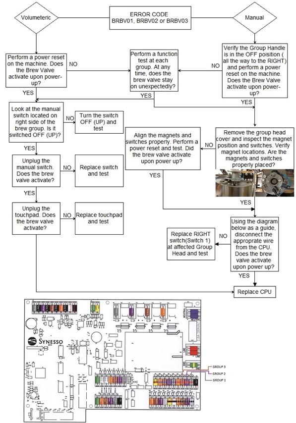
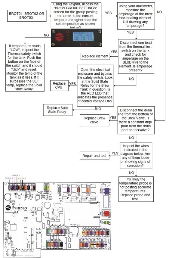
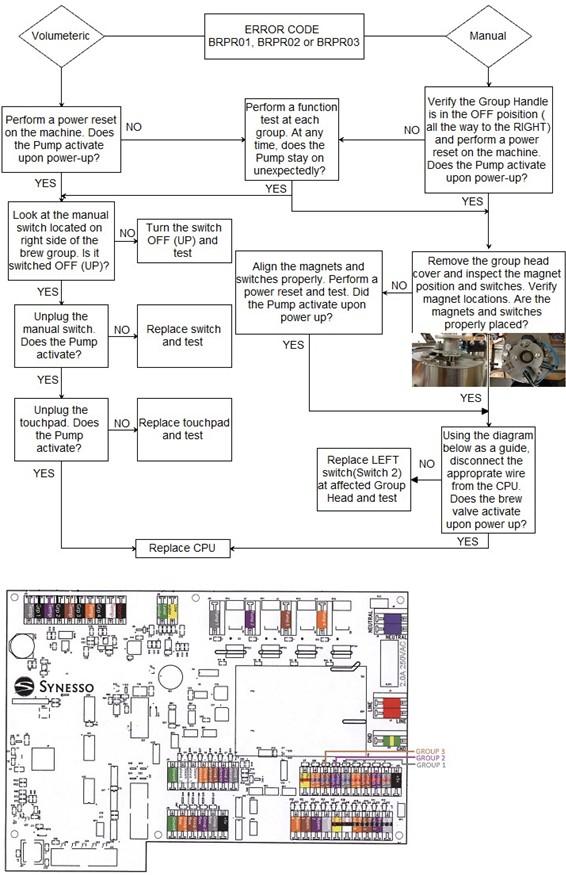
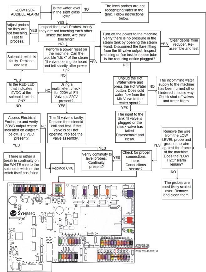
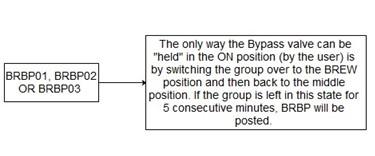
37 PROGRAMMING Error codes are displayed here In an effort to prevent damage to machines and to help operators troubleshoot issues, Synesso has engineered several safeguards into the programming. These codes will help users identify operational issues with the machine as well as automatically prevent greater problems from occurring. By understanding these codes, operators can remedy issues more quickly. Error code key (See Pages for more info) BR Brew System Codes BV Brew Valve has been on for 5 minutes. Valve will be disabled until group is turned off. OT Over Temperature. (220F) UT Group reads under 180F for 1 minute while trying to heat (Under Temp.) PR Pump Relay coil has been on for 5 minutes. Relay will be disabled until group is turned off. BP Bypass Valve has been held on for 5 minutes. Valve will be disabled until group is turned off. 01, 02, or 03 Indicate which brew group is reporting an error. ST Steam System Codes LW Low Water probe is not in contact with water (an audible alarm will also sound) FP Fill Probe is not in contact with water for 1 minute. FV Fill Valve has been held on for 5 minutes. Valve will be disabled until machine is turned off. OT Over Temperature (270F) 01 All Steam System Codes end in 01 VM Volumetric System Codes UF Unexpected flow while group is off. 01, 02, or 03 Indicate which flow meter is reporting an error. Example: After brewing a shot, group 2 was left in the brew position. After 5 minutes, the machine will register a BRBV02 and a BRPR02 error; which translate to Brew System, Brew Valve Group 2 and Brew System, Pump Relay is timed out, Group 2. At this time the machine will automatically shut off both the brew valve and the pump relay to ensure they will not be damaged. They will remain off until the group is returned to the off (far right) position, which allows the group to return to normal operation. 37
38 38
39 39
40 40
41 41
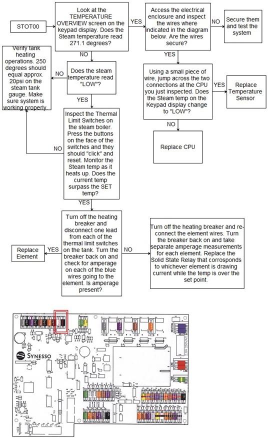
42 PROGRAMMING STEAM SYSTEM ERROR CODES With regard to the error codes associated with water level control, there is a cascading effect as the water level in the boiler drops. For example, if the water inlet to the tank is clogged or the fill solenoid fails, the system will be unable to re-fill the boiler. Look at the timeline of this scenario below: This timeline shows that all three error codes will be posted for this issue. The time it takes for the water level to drop below the LOW LEVEL probe and post the LOW H2O error depends upon the water and steam usage of the machine during operation. The following flowchart will begin with the LOW H2O heading because that is the error likely to be seen on a machine that has ceased to heat the boilers. However, the flowchart will cover all three of these Error codes as they are all tied to the same general issue. To view the timeline of these failures on the wired display, access the Level 2 Programming and scroll to the ERROR LOG screen. Once there, the Date/Time stamps can be viewed for all past errors on the machine. Use the up and down arrows to scroll through errors. 42
43 43
44 44
45 45

46 PROGRAMMING There are 3 menu levels accessible to technicians. Menu level 2 may only be reached from level 1 and level 3 may only be reached from level 2. To access menu level 2 - From the Temperature Overview screen, press and hold both the line 4 button and up arrow, for approximately 4 seconds. The screen will cycle to the Temperature Display screen. This is screen 1 of menu level 2. Menu Level 2: Temperature Display Line 1 indicates that you are on the Temperature Display screen. Line 2 indicates the Temperature scale that you are currently in (Fahrenheit or Celsius). Line 4 indicates the operation status of the machines Brew Valve(s). To Change between temperature scales, press the button associated with line 2. Use the buttons to select the desired scale (Fahrenheit/Celsius), followed by the line 2 button once again to confirm the selection. All temperature readings on the machine will now be in the selected scale. The Brew Valves can be set to the [ON] or [NORMAL] position in order to help with draining the brew groups. Setting the Brew Valve function to the [ON] indicator will activate the brew valves, allowing the pressure to be bled from the brew group(s). Once the pressure is bled, turn the Brew Valve setting back to [NORMAL] and attach the appropriate drain hose to the brew groups drain tube. Set the Brew Valve indicator back to [ON] once the drain hoses are securely attached. This will allow the water in the brew group(s) to fully drain in approximately 5 minutes. When the brew groups are finished draining, set the Brew Valve indicator back to the [NORMAL] setting. If the draining process takes longer than 5 minutes, the machines safety programming will automatically turn the brew Valve indicator to the [NORMAL] setting while exiting back to the Display Default Overview screen. An error message will also be sent to the Error Log that the brew valves have timed out. If more time is needed, return to the Temperature Display screen and set the Brew Valve display back to the [ON] position to finish the procedure. To set the brew valves to [ON] or back to [NORMAL], press the button associated with line 4. Use the buttons to select the desired operation mode, followed by the line 4 button once again to confirm the selection. Once finished with the draining procedures, make sure the Brew Valve indicator is set back to the [NORMAL] position. To cycle to the next display screen press the button to the left of line 1. 46

47 PROGRAMMING Menu Level 2: Steam Tank Fill Probe Line 1 indicates that you are on the Steam Tank Fill Probe control screen. Line 2 of this display screen is showing a 5 second delay indicating that the fill probe will wait this long before turning on or off the steam tank fill valve. To change the delay time, press the button associated with line 2. Use the buttons to select the desired time and then confirm the selection. To cycle to the next display screen press the button to the left of line 1. 47
48 PROGRAMMING Menu Level 2: Brew Group 1 Offset Line 1 indicates that you are now in the Brew Group 1 Offset screen. Line 2 indicates the actual water temperature at the selected brew group s temperature probe as it is maintaining your Set Temperature. Line 3 represents the actual temperature reading of water flow through the puck. Line 4 indicates the temperature adjustment made at the Synesso factory, in order to create the exact temperature desired at the puck. Puck Temperature on line 3 is determined at the factory, according to the standard Synesso testing method. Adjustment to this setting is not recommended without thorough testing. The Synesso testing method is as follows: Using a bottomless portafilter, dose out grams of coffee into a 14 gram basket with a thermal probe inserted 1/8th of an inch from the surface and in the middle of the puck, packing and tamping the grounds in the basket as usual. The thermal probe is then wired to a FLUKE thermometer to relay the actual temperature of the water flowing through the puck while pouring a 2 ounce shot. This process is repeated a minimum of 3 times per brew group in order to get the most accurate reading. This reading is then applied to line 3 by pressing the corresponding button. Use the buttons to select the desired setting and then confirm the selection. Inserting the temperature on line 3 will automatically set the line 4 offset. The Offset on line 4 can be altered to achieve the same effect as inputting a temperature on the Puck temperature line. Changing the offset will correspondingly alter the puck temperature. This offset point should not be altered without thoroughly testing the puck temperature, as mentioned above. To cycle to the next display screen press the button to the left of line 1. 48
49 PROGRAMMING Menu Level 2: Steam Tank Offset Line 1 indicates that you are on the Steam Tank Offset screen. Line 2 indicates the actual water temperature at the steam tank temperature probe, as the electronics maintain your Set Temperature. Line 4 indicates the temperature adjustment made at the Synesso factory, in order to create the exact temperature desired in the steam tank. This offset should not be altered without first consulting Synesso. To cycle to the next display screen press the button to the left of line 1. Menu Level 2: System Clock Line 1 indicates that you are currently on the System Clock screen. Line 2 indicates the programmable time for the machine in a 24 hr format. Line 3 indicates the programmable date settings. Line 4 stores the programmed date in the format indicated on line 3 Press the line 2 button followed by the buttons to make appropriate adjustments to the 24 hr clock so that any alarms programmed will work correctly. To adjust line 4, press the corresponding button followed by the buttons to select the appropriate date. To cycle to the next display screen press the button to the left of line 1. 49
50 PROGRAMMING Menu Level 2: Power Save Mode Setup Line 1 indicates that you are on the Power Save Mode screen. Line 2 of the Power Save Mode in this example is indicating the timers are [ENABLED], making adjustments to lines 3 and 4 available. If line 2 reads [DISABLED], no further programs will be available on this screen. Line 3 indicates the settable time at which your power save mode will start. Line 4 indicates the settable time at which your power save mode will end. Enabling the power save mode will drop the temperature in the brew group(s) to 180F (82.2C) and the steam tank to 220F (104.4C) for the time span set. This will help conserve energy while preventing maintenance issues that occur due to depressurizing and re-pressurizing, when machines are turned off and on. This will also allow the machine a shorter amount of time to reach full temperature and stabilize, after the power save mode has ended. We suggest using this feature only if the machine can be in power save mode for more than 3 hours at a time. To cycle to the next display screen press the button to the left of line 1. 50
51 PROGRAMMING Menu Level 2: Error Log Line 1 indicates that you are on the Error Log screen. Line 2 indicates the last error that occurred. If no error has occurred, this line will simply read NO ERROR. Line 3 indicates the date and time that the last error has occurred. If no error has occurred, this line will be blank. Line 4 gives the option to clear the Error Log. To cycle through the Error Log, use the buttons. Cycling through the Error Log will change the date and time on line 3 to match the displayed Error Code time of occurrence. To clear the Error Log, press the button associated with line 4. See page 37 for descriptions of the error codes you may see. To cycle to the next display screen press the button to the left of line 1. Menu Level 2: Return To Level 1 Line 1 and 2 indicate that you are on the Return To Operation Mode screen. Pressing the line 1 button will cycle back to the Temperature Display screen on menu level 2. Pressing the line 3 button will cycle back to menu level 1 s Display Default Overview screen. Access to level 3 is only available from this screen. To reach menu level 3 - press and hold both the line 4 button and the up arrow at the same time. The screen will cycle to the Volumetrics screen which is screen 1 of level 3. 51
52 PROGRAMMING Menu Level 3: Volumetrics Volumetric functions (such as Automatic Bypass) are only applicable on machines with volumetric hardware. If the machine has volumetric hardware installed, this indicator should be left [ON]. Menu Level 3: Brew Groups The Brew Groups Present will be set to correspond directly to the physical definition of your machine and should not be altered. 52
53 PROGRAMMING Menu Level 3: Reset The Full Reset to Defaults option can be achieved by pressing the line 3 button. This option will undo ALL changes that have been made to the machine. This includes the Synesso programmed offsets, serial number and machine configuration information. It is highly recommended that you make note of all Synesso programmed settings before doing a full reset of the machine. Reset cannot be undone. Be careful. Menu Level 3: Bypass The Bypass Hardware on the pump can be activated and deactivated from this screen. If your machine has bypass hardware installed, this setting should be [ON], as indicated above. Menu Level 3: Hydra In the case of a Hydra / Hybrid, the correct pump configuration is [MULTIPLE]. Cyncra and Sabre models use [SINGLE]. 53
 is a sequence of algorithms using separate, finely tuned parameters to achieve a desired set point.")
54 PROGRAMMING Menu Level 3: PID Tune Line 1 indicates that you are on the PID Tune screen. The proportional integral derivative controller (PID controller) is a sequence of algorithms using separate, finely tuned parameters to achieve a desired set point. Synesso strongly recommends against altering these parameters. Line 2 indicates the P Gain (Proportional Gain) value. Line 3 indicates the I Gain (Integral Gain) value. Line 4 indicates the D Gain (Derivative Gain) value. The default values are shown in the picture above. Menu Level 3: Serial Number The Machine Serial Number is the designated identification given to the machine according to the month/year and order of completion. This method of identification may be used to help diagnose any issues or determine any specific needs that may arise during the life of this machine. For this reason, the machine serial number should not be altered. 54
55 PROGRAMMING Menu Level 3: Return Line 1 indicates that you are on the Return screen Line 2 will return to menu level 1 (Operation menu). Line 3 will return to menu level 2 (Settings menu). 55

56 PROGRAMMING VOLUMETRIC PROGRAMMING This section contains instructions for programming the volumetric dosing on Sabre machines and Hybrid machines with volumetric group heads. Basic machine programming is found on page 31. Shot buttons Pitcher / continuous flow button To enter programming mode, press and hold any 2 shot buttons. After 3 seconds, the indicators for each button will illuminate. At this point, you can press the continuous flow (or pitcher) button on one or more groups to exclude that specific group from programming. This will turn off the upper indicators on the deselected group. A red indicator will remain lit on the deselected group s continuous flow button. Pressing this button again will exit the programming mode. If a group has been deselected in error, you must exit and reenter programming mode to re-select the group for programming. While in programming mode, press any shot button with a lit indicator to begin a shot. As the shot flows, the indicator at each button receiving a program will blink. Once the desired volume has been reached, press the same shot button a second time to end the shot. The indicator light(s) will turn off. You may now program another button or exit the programming mode. If an error has been made, you may reprogram a button without leaving programming mode. Pressing a previously programmed button overrides the original program. To exit the programming mode, press any continuous flow button on a deactivated group. As noted above, pressing a continuous flow button on an active group will deactivate it. When you exit programming mode, all lit indicators will turn off. Notes: o The continuous flow / pitcher button cannot be programmed. During normal operation, pressing the pitcher button will stop a currently flowing shot, or start a continuous flow of water from the group. o Any stage 1 or 2 times (see Programming, page 17) set up prior to entering volumetric programming mode will be active during programming. Water dispensed during stage 1 and 2 counts toward total shot volume. o Shot timers, if present, are not active during volumetric programming. The timers return to normal function once the machine leaves programming mode. Low Flow Error: o If a shot button is pressed but flow is not detected by the flow meters, the two indicators on the pitcher button will light and flash. If inadequate flow persists for 30 more seconds, the brew valve will close, cancelling the shot. The lights will continue to flash and the group cannot be used until the low flow error has been acknowledged by pressing the pitcher button. The most common reason for this error will be grind/tamp mistakes, but the incoming water may be restricted. If this error occurs frequently, please check the incoming water lines. 56
Owner s Manual Cyncra and Hydra Espresso Machines
 Artistry Ingenuity Understanding Owner s Manual Cyncra and Hydra Espresso Machines Safety Warnings IMPORTANT Information for the Cyncra and Hydra Espresso Machine Manufactured by Synesso, Inc. DISCONNECT
INSTALLATION & OPERATING GUIDE
 SURE TAMP STEAM INSTALLATION & OPERATING GUIDE BUNN-O-MATIC CORPORATION POST OFFICE BOX 3227 SPRINGFIELD, ILLINOIS 6278-3227 PHONE: (217) 529-661 FAX: (217) 529-6644 http://www.bunn.com/espresso/index.html
1. IMPORTANT SAFEGUARDS When using electrical appliances, basic safety precautions should always be followed to reduce the risk of fire, electric
 1. IMPORTANT SAFEGUARDS When using electrical appliances, basic safety precautions should always be followed to reduce the risk of fire, electric shock, and/pr injury to persons including the following:
E N T E R P R I S E S
 N E W C O E N T E R P R I S E S P/N 110881 Issued 12/99 INSTALLATION and OPERATION MANUAL for OCS-16A BREWERS BREWER SPECIFICATIONS Model Width Length Height US 120V Amps CANADA 120V Amps OCS-16A 14 15-1/2
MVP & MVP HYDRA OWNERS MANUAL VERSION
 MVP & MVP HYDRA OWNERS MANUAL VERSION 2018.1 Last Revision: October 2018 3 Group MVP 5610 4th Ave S. / Seattle, WA 98108 USA Tel: +1 206 764 0600 / Fax: +1 206 764 0601 Ordering Parts: parts@synesso.com
INSTALLATION and OPERATION MANUAL for GXD SERIES BREWERS
 Man Pt No 701859 Rev 3-01 INSTALLATION and OPERATION MANUAL for GXD SERIES BREWERS GXDF2-30 GXDF-8D Model BREWER SPECIFICATIONS No of Warmers Width Length Height* US 120V Amps US 120/240V Amps Phase GXDF2-15
Wega Mininova 2003 Installation Instructions
 Wega Mininova 2003 Installation Instructions Thank you for purchasing a Wega Espresso Product. We are sure you will be happy with your purchase and the quality of coffee produced by our machines and grinders.
SYNESSO S200 OWNERS MANUAL VERSION
 SYNESSO S200 OWNERS MANUAL VERSION 2018.2 Last Revision: August 2018 5610 4th Ave S. / Seattle, WA 98108 USA Tel: +1 206 764 0600 / Fax: +1 206 764 0601 Ordering Parts: parts@synesso.com Information: info@synesso.com
User Manual. Stainless Steel Coffee Urns. Models: 177CU55ETL, 177CU110ETL 10/2016. Please read and keep these instructions. Indoor use only.
 Intertek Stainless Steel Coffee Urns Models: 177CU55ETL, 177CU110ETL 10/2016 Please read and keep these instructions. Indoor use only. www.avantcoequipment.com 1 NOTE: Save these instructions for future
BREW EXPRESS OPERATION GUIDE MODEL BE112
 BREW EXPRESS OPERATION GUIDE MODEL BE112 Contents 1. Safety 2. Features 3. Controller Functions 4. Start up 5. Operation 6. Maintenance 7. Troubleshooting 8. Parts & Service 9. Warranty & Registration
5KEK1322 W A_v08.indd 1 5/13/16 2:25 PM
 5KEK1322 W10878653A_v08.indd 1 PARTS AND FEATURES PARTS AND ACCESSORIES Tea steeper lid (center section of lid with handle) Kettle lid (outer section) Stainless steel lime scale filter Removable stainless
OPERATING INSTRUCTIONS FOR YOUR SAFETY CAREFULLY READ THE OPERATING INSTRUCTIONS. FOR HOUSEHOLD USE ONLY
 OPERATING INSTRUCTIONS FOR YOUR SAFETY CAREFULLY READ THE OPERATING INSTRUCTIONS. FOR HOUSEHOLD USE ONLY 2 Opening Congratulations on choosing this high quality espresso machine and thank you for your
User Manual. Stainless Steel Coffee Urns. Models: 177CU30, 177CU55, 177CU110 04/2018. Please read and keep these instructions. Indoor use only.
 Stainless Steel Coffee Urns Models: 177CU30, 177CU55, 177CU110 04/2018 Please read and keep these instructions. Indoor use only. www.avantcoequipment.com 1 NOTE: Save these instructions for future reference.
User Manual. Stainless Steel Coffee Urn. Models: 177CU30 11/2018. Please read and keep these instructions. Indoor use only.
 Stainless Steel Coffee Urn Models: 177CU30 11/2018 Please read and keep these instructions. Indoor use only. www.avantcoequipment.com 1 NOTE: Save these instructions for future reference. Index Important
OPERATING MANUAL. Sample PRO 100 Series. Electric Heating. Applies to Versions: SPE1*, SPE2, SPE4, SPE6
 OPERATING MANUAL Sample PRO 100 Series Electric Heating Applies to Versions: SPE1*, SPE2, SPE4, SPE6 NOTE: All electrically heated roasters in the Sample PRO 100 Series are modular and this manual applies
Quick Start Guide Read this booklet thoroughly and save these instructions.
 Quick Start Guide Read this booklet thoroughly and save these instructions. FAQs can be found at www.espresso-works.com Email us for any unanswered questions: cs@espresso-works.com For product registration,
E N T E R P R I S E S
 N E W C O E N T E R P R I S E S 2Man Pt No 701528 REV 10-01 INSTALLATION and OPERATION MANUAL for GX SERIES BREWERS GXF3-15 GXF-8D Model BREWER SPECIFICATIONS No of Warmers Width Length Height* US 120V
Shotmeister Owner s Manual. The Sleekest Design, Pouring the Coldest Shots
 Shotmeister Owner s Manual The Sleekest Design, Pouring the Coldest Shots Thank you for purchasing a Jägermeister Shotmeister! REGISTRATION INFORMATION Register your Jägermeister Shotmeister Online: at
BREW EXPRESS OPERATION GUIDE. model no. BE-112
 BREW EXPRESS OPERATION GUIDE model no. BE-112 by CONTENTS 1. Safety 1 2. Features 2 3. Controller Functions 3 4. Start Up 4 5. Operation 5 6. Maintenance 6 7. Troubleshooting 7 8. Parts & Service 8 9.
Models 2450 & Espressimo TM Espresso Cappuccino Machines. Operation & Installation Manual TABLE OF CONTENTS. For
 Espressimo TM Espresso Cappuccino Machines Operation & Installation Manual For Models 2450 & 1750 *Also includes information & instructions for Q & E models. TABLE OF CONTENTS Warning Labels...2 Initial
PLEASE READ THIS MANUAL BEFORE USE. SAVE FOR FUTURE REFERENCE.
 8-CUP STAINLESS STEEL CARAFE Coffee Brewer Model: BV1900TS HOUSEHOLD USE ONLY Customer Service Line: 1-855-664-1252 2-year limited warranty bonavitaworld.com Simple to operate Optional pre-infusion cycle
Electric Two-Speed Drink Mixer
 Electric Two-Speed Drink Mixer MS2090 Series Before use, please read this manual thoroughly and save for future reference. ovente.com Electric Two-Speed Drink Mixer MS2090 Series 2 ovente.com ELECTRIC
Installation and User Instructions Flushing System Kit
 Installation and User Instructions Flushing System Kit Model: ACFS Part No. 102532 Rev. A Copyright 2007 Dacor All rights reserved. All specifications are subject to change without notice. Dacor assumes
CafeRomatica NICR7.. Fully automatic coffee centre Operating Instructions and Useful Tips. A passion for coffee.
 CafeRomatica Fully automatic coffee centre Operating Instructions and Useful Tips NICR7.. GB A passion for coffee. 1 G F A M J / K A B C D E Display screen Left rotary knob Right rotary knob Bean symbol
TEA CATER USER MANUAL. UM_EN Part No.:
 USER MANUAL UM_EN Part No.: 1730080-02 CONTENT CONTENT... 2 GENERAL... 4 Introduction...4 Warnings...4 Precautions...4 Intended use...4 Facts & weight...5 General functional description...5 OVERVIEW OF
MODEL: POD BREWER AURORA SAF 68 HOMEMAKER ESPRESSO MAKER WITH COFFEE POD
 INSTRUCTION MANUAL Please read this Instruction Manual and the safety instructions before operating the appliance! MODEL: POD BREWER AURORA SAF 68 HOMEMAKER ESPRESSO MAKER WITH COFFEE POD Congratulation
Pellet Pro 12 & 18 Lengths Large 35lb Hopper Assembly Operation Manual
 Pellet Pro 12 & 18 Lengths Large 35lb Hopper Assembly Operation Manual Now with our exclusive PID Controller & Universal Mounting Capabilities! FOR OUTDOOR USE ONLY Disclaimer: The hopper assembly is used
EXPOBAR OFFICE MACHINES
 EXPOBAR OFFICE MACHINES Supplemental Instructions Includes brewing guide, frothing techniques and recipes. These are supplemental instructions for the Expobar Office Control, Pulser and Lever. They are
INSTALLATION AND WARRANTY CERTIFICATE. Machine model Serial Number # Rating and optional. Installation Company: Technician ID: Date: / /
 INSTALLATION AND WARRANTY CERTIFICATE Machine model Serial Number # Rating and optional Installation Company: Technician ID: Date: / / Water-Line Pressure: NOTE: over 5bar/70psi, a pressure regulator must
12 CUP COFFEEMAKER User Guide
 BRAND 12 CUP COFFEEMAKER User Guide Item: 757147 Ginnys.com 800-544-1590 Facebook.com/GinnysBrand Pinterest.com/GinnysBrand Welcome to the world of full-flavored coffee with the Ginny s Brand 12-Cup Coffeemaker!
AS450, AS600, G1, SG630
 Grill Range Operating Manual Grill Range AS450, AS600, G, SG60 Product Range Also Includes: Induction Hobs / Combination Ovens / Pizza Ovens / Mixers Salamander Grills / Contact Grills / Pie Warmers /
Micro Casa Semiautomatica
 Micro Casa Semiautomatica Training Manual Contents Overview 1 Models 1 Specifications 1 Features 1 Available accessories 1 Package contents 2 Semiautomatic parts 3 Assembly 4 Operating instructions 4 Starting
12 CUP COFFEE MAKER User Guide
 BRAND 12 CUP COFFEE MAKER User Guide Item: 740553 Ginnys.com 800-544-1590 Facebook.com/GinnysBrand Pinterest.com/GinnysBrand Ginnys.com/Blog Welcome to the world of full-flavored coffee with the Ginny
Micro Casa a Leva Training Manual
 Micro Casa a Leva Training Manual Contents Overview 1 Models 1 Specifications 1 Features 1 Available accessories 1 Package contents 2 Leva parts 3 Assembly 4 Operating instructions 4 Making coffee 5 Procedure
Triple Brew. Model #352. Coffee & Tea Maker. Instructions Warranty
 Triple Brew Coffee & Tea Maker Model #352 Instructions Warranty IMPORTANT SAFEGUARDS When using electrical appliances, basic safety precautions should always be followed, including: 1. Read all instructions.
Installation/Operation Manual
 Installation/Operation Manual FC-S3 FC-5 FC-3 FC-TD FC-AP FC-LD FC-S FC SERIES BREWERS FC-TS Oct. 18, 17 NEI 1.800.325.7867 www.newcocoffee.com P a g e 1 Table of Contents Plumber s Install Instructions
INSTALLATION QUICK START GUIDE AND CHECKLIST ATTENTION!! DO NOT ATTEMPT A PARTIAL INSTALL.
 AND CHECKLIST CHECKLIST MUST BE SIGNED AND RETURNED TO RANCILIO GROUP NA TO RECEIVE PAYMENT FOR YOUR SERVICES ATTENTION!! Please check the site to make sure they are ready for installation before you begin
STAINLESS STEEL MILK FROTHER. Model: PKFMR11BK
 STAINLESS STEEL MILK FROTHER Model: PKFMR11BK WARNING! To reduce the risk of fire, electrical shock or injury to persons or property: Carefully read all instructions before operating your new product for
CAIMANO SPECIAL450 BARISTA
 ANFIM ANFIM Srl Via B. Verro, 33/5-20141 - MILANO ITALY Tel. (+39) 02/8465054 - Fax.(+39) 02/8464401 e-mail: info@anfim.it web site: www.anfim.it COFFEE GRINDER INSTRUCTIONS MANUAL mod: CAIMANO SPECIAL450
Lusso / Espresso Si' Models:PL-16 PAB-16. Made In Italy
 Lusso / Espresso Si' Models:PL-16 PAB-16 Made In Italy la pavoni - PL-16 & PAB-16 We recommend using freshly roasted espresso beans ground medium to fine. Fresh coffee will produce better tasting espresso.
5KEK1522 W A_01_EN.indd 1 11/16/12 1:22 PM
 5KEK1522 Water Kettle INSTRUCTIONS Table of Contents water KEttle SAFETY Important safeguards...6 Electrical requirements...7 Electrical equipment waste disposal...7 PARTS AND FEATURES Parts and accessories...8
Coffee System Troubleshooting and Repair
 Coffee System Troubleshooting and Repair Page 30 CM24-1 Operation Sequence POWER ON/OFF When turning on the coffee system the brewer motor cycles once and the display reads Please Wait Heating, Once heating
IMPORTANT SAFEGUARDS. 3. To protect against fire, electric shock and injury to persons do not immerse cord, plug or unit in water or other liquid.
 IMPORTANT SAFEGUARDS When using electrical appliances, basic precautions should always be followed, including the following: 1. Read all instructions. 2. Make sure that your outlet voltage corresponds
Thank you for your purchase!
 CM4200S Thank you for your purchase! www.prodprotect.com/blackanddecker Should you have any questions or concerns with your new product, please call our Customer Service Line at 1-800-465-6070 (US and
Installation & Parts Manual 2" & 3" High Capacity Strainers For Class 1, Petroleum Applications
 Installation & Parts Manual 2" & 3" High Capacity Strainers For Class 1, Petroleum Applications Installation: M200-20 www.lcmeter.com Table of Contents Description Page Number Introduction... 2 What LC
5KCG0702 W A_Final.indd 1 8/4/15 8:35 AM
 5KCG0702 PARTS AND FEATURES PARTS AND ACCESSORIES Hopper lid Easy access stainless steel burrs 200 g glass hopper 15 grind settings Die cast metal body Grind control dial Power switch Faceplate assembly
SG120 Model # Cup Stainless Steel Coffee Maker. Operating Instructions Product Registration Warranty
 SG120 Model #494 12-Cup Stainless Steel Coffee Maker Operating Instructions Product Registration Warranty IMPORTANT SAFEGUARDS When using electrical appliances, basic safety precautions should always be
A N F I M Srl. Caimano: Timer / Automatico / Manuale Super Caimano: Timer / Automatico Caimano SPecial 450: Timer / Automatico
 ANFIM A N F I M Srl Via B. Verro, 33/5-204 - Tel. (+39) 02/8465054 e-mail: info@anfim.it MILANO ITALY - Fax.(+39) 02/846440 web site: www.anfim.it GB INSTRUCTIONS MANUAL mod: Caimano: Timer / Automatico
COFFEE MAKER INSTRUCTION MANUAL CM4682-V
 COFFEE MAKER INSTRUCTION MANUAL CM4682-V IMPORTANT SAFEGUARDS Before using the electrical appliance, the following basic precautions should always be followed including the following: 1. Read all instructions.
1550W DIGITAL FRENCH DOOR OVEN Instruction Manual MODEL CCFD19
 1550W DIGITAL FRENCH DOOR OVEN Instruction Manual MODEL CCFD19 1 WHAT S INCLUDED French Door Oven & Instruction Manual Rotisserie Hle Two Wire Racks Baking Pan Rotisserie Tray Hle Crumb Tray 2 IMPORTANT
A N F I M Srl. Caimano On Demand. Super Caimano COFFEE GRINDER C O D Y S C O D Y - II. Model
 ANFIM A N F I M Srl Via B. Verro, 33/5-20141 - Tel. (+39) 02/8465054 e-mail: info@anfim.it MILANO ITALY - Fax.(+39) 02/8464401 website: www.anfim.it INSTRUCTION MANUAL Model Caimano On Demand Super Caimano
Automatic Cold Brewer
 Automatic Cold Brewer Model# GCM-6800 USER MANUAL Read this manual thoroughly before using and save it for future reference Model: GCM-6800 2017 Gourmia www.gourmia.com The Steelstone Group Brooklyn, NY
The Scoop 2-Way Brewer
 READ BEFORE USE The Scoop 2-Way Brewer Visit www.hamiltonbeach.in for our complete line of products and Use and Care Guides as well as delicious recipes, tips, and other helpful information! Questions?
DISCONTINUED VERSION The information in this manual is no longer current. Espresso/Cappuccino OPERATING & SERVICE MANUAL BUNN-O-MATIC CORPORATION
 BUNNEspress BUNN Espress DISCONTINUED VERSION The information in this manual is no longer current. Espresso/Cappuccino OPERATING & SERVICE MANUAL BUNN-O-MATIC CORPORATION POST OFFICE BOX 3227 SPRINGFIELD,
Installation Instructions Built-In Coffee Maker
 Installation Instructions Built-In Coffee Maker Single Double Espresso Espresso Single Latté Hot Double Decaf Large Cappuccino Latté Coffee Coffee Steamer Water E24CM75GSS e24cm76gss 102221 Rev. C-2 2
OWNERS MANUAL. My Rotisserie Pro Warranty. Please read and save this manual. PROFESSION AL SERIES MRP_MAN_QVC_ENG_V1_ FOR HOUSEHOLD USE ONLY.
 My Rotisserie Pro Warranty The manufacturer warrants that your My Rotisserie Pro is free of defects in materials and workmanship and will, at its option, repair or replace any defective rotisserie that
MODELS 1315 & 1315-S La Pavoni CLUB COMBO
 IMPORTANT WARNINGS MODELS 1315 & 1315-S La Pavoni CLUB COMBO DUET Never operate your espresso machine without water in the tank. This may cause premature pump failure. Do not allow the power cord to come
COLD BREW COFFEE MAKER. Model# GCM-7800 USER MANUAL
 COLD BREW COFFEE MAKER Model# GCM-7800 USER MANUAL Read this manual thoroughly before using and save it for future reference FOR CUSTOMER SERVICE QUESTIONS OR COMMENTS VISIT US @ GOURMIA.COM INFO@GOURMIA.COM
PARTS CATALOG ESPRESSO EP SYSTEM
 PARTS CATALOG ESPRESSO_EP_Parts_Catalog_USA_V1.0 - p1-4 1 Contents DIMENSIONS 3 SPECIFICATIONS 4 ESPRESSO TAP 5 ESPRESSO MODULE 9 ESPRESSO_EP_Parts_Catalog_USA_V1.0 - p1-4 2 137 mm 5.4 in. 414 mm 16.3
HANDMADE IN FLORENCE GS/3. Software Programming Guide. Version 1.09
 HANDMADE IN FLORENCE GS/ Software Programming Guide Version.09 GS/ Table of Contents Programming Introduction Programming Keypad... Digital... Accessing Programming Mode Programming Mode... Initial Installation
Coffee Grinder Instruction Manual
 Coffee Grinder Instruction Manual CoffeeGrinder Manual-English Only.indd 1 07/01/2016 14:14:39 Savisto Home Coffee Grinder Voltage Supply: 220-240V~ 50/60Hz Power Consumption: 150W Eng Please read through
G F I M J K L B C D E S O T H Q P U N R D 4
 1 2 3 4 G F I A M J K L 5 6 7 B C D E 8 9 10 S O T H Q P U N R 11 12 D 4 Equipment GB A B C D E Text display (main menu) Rotary control knob Button > Button exit Height-adjustable coffee spout CafeRomatica
BREW EXPRESS IMPORTANT NOTE: model no. BE-104 & BE-110. For more information see our instructional video online at
 BREW EXPRESS Operation GUIDE model no. BE-104 & BE-110 IMPORTANT NOTE: For more information see our instructional video online at www.brewexpress.com. Do not return this product to place of purchase without
Programmable Conical Burr Mill CBM-18
 Programmable Conical Burr Mill CBM-18 IMPORTANT SAFEGUARDS When using electrical appliances, basic safety precautions should always be followed, including the following: 1. Read all instructions. 2. To
Operator Manual 100 Series Coffee Grinders
 Operator Manual 100 Series Coffee Grinders Models 100 and 190SS Model 100 Model 190SS Specifications...2 Safety Information...2 Installation...3 Operation...3 Table of Contents Cleaning & Maintenance...6
CMC DUO. Standard version. Table of contens
 CMC DUO Standard version O P E R A T I N G M A N U A L Table of contens 1 Terminal assignment and diagram... 2 2 Earthen... 4 3 Keyboards... 4 4 Maintenance... 5 5 Commissioning... 5 6 Machine specific
Get Started. Better Everyday ECAM23260
 Better Everyday Get Started This short guide is not intended to explain all the functions of the appliance. Please read all the owner s instruction booklet before use. Video available on www.youtube.com/delonghiusa
PORTABLE ESPRESSO MACHINE. Compatible Ground Coffee only. Designed by
 GR PORTABLE ESPRESSO MACHINE Compatible Ground Coffee only Designed by Dear Customer, Thank you for having chosen our product and for your confidence in our company. We have devoted all our knowledge,
EXPOBAR BREWTUS III Supplemental Instructions
 EXPOBAR BREWTUS III Supplemental Instructions www.wholelattelove.com 888.411.5282 1 Congratulations on the purchase of your new Brewtus III R or Brewtus III V! The Expobar Brewtus is a very unique machine
Downflow Conversion Kit used to Modify Air Handler Units for Downflow Application
 0672327-00 February 2015 Installation Instructions Downflow Conversion Kit used to Modify Air Handler Units for Downflow Application Scan to see the Downflow Installation Video Go to your app store and
User Guide TEA CATER. Your Dealer. U / EN Rev
 User Guide TEA CATER Your Dealer U / EN Rev 101115 1. Contents Tea Cater 1. Contents page 2 2. General 3 3. Function description 3 4. Start-up 3 5. Component overview 4 5. Function button overview 5-6
Manual Spark Ignition (MSI) Kit For Use only with Thermocouple Manual Safety (TMSI) UL Approved Fire Pit Pans with Burning Spur
 Kit For Use only with Thermocouple Manual Safety (TMSI) UL Approved Fire Pit Pans with Burning Spur") AAA Battery MODEL: MSI-BSTMSI Manual Spark Ignition (MSI) Kit For Use only with Manual Safety (TMSI) UL Approved Fire Pit Pans with Burning Spur Installation and Operating Instructions IF YOU CANNOT READ
AAA Battery MODEL: MSI-BSTMSI Manual Spark Ignition (MSI) Kit For Use only with Manual Safety (TMSI) UL Approved Fire Pit Pans with Burning Spur Installation and Operating Instructions IF YOU CANNOT READ
SERVICE MANUAL ESPRESSO COFFEE BREWER UNITS
 AFTER-SALES SERVICE SERVICE MANUAL ESPRESSO COFFEE BREWER UNITS Z 3000V (with variable brewing chamber) Z-3000 var 13/10/2005 page 1 / 11 ESPRESSO COFFEE BREWER UNITS Z 3000 V ESPRESSO The espresso coffee
Wi-Fi Coffee Maker. Model# GCMW-4750 USER MANUAL
 Wi-Fi Coffee Maker Model# GCMW-4750 USER MANUAL Read this manual thoroughly before using and save it for future reference Model: GCMW-4750 2018 Gourmia www.gourmia.com The Steelstone Group Brooklyn, NY
INSTRUCTION MANUAL MODELS: RT-30, RT-36, RT-48, RT-60 & RT-72 REVISED APRIL, 2003 *PLEASE RETAIN FOR FUTURE REFERENCE
 INSTRUCTION MANUAL MODELS: RT-30, RT-36, RT-48, RT-60 & RT-72 REVISED APRIL, 2003 *PLEASE RETAIN FOR FUTURE REFERENCE THANK YOU for purchasing this quality product. Your Crown Verity Inc. rotisserie will
 EXPOBAR BREWTUS IV Supplemental Instructions for all Expobar Brewtus IV machines Rotary Pump (IV-R), Vibration Pump(IV), Plumbable Vibration Pump (IV-P) www.wholelattelove.com 888.411.5282 1 Congratulations
MG600 PLUS, Model #484 (Glass) 10-Cup Programmable Coffee Maker with Stainless Steel Housing. Operating Instructions Product Registration Warranty
 10-Cup Programmable Coffee Maker with Stainless Steel Housing. Operating Instructions Product Registration Warranty") MG600 PLUS, Model #484 (Glass) 10-Cup Programmable Coffee Maker with Stainless Steel Housing Operating Instructions Product Registration Warranty IMPORTANT SAFEGUARDS When using electrical appliances,
MG600 PLUS, Model #484 (Glass) 10-Cup Programmable Coffee Maker with Stainless Steel Housing Operating Instructions Product Registration Warranty IMPORTANT SAFEGUARDS When using electrical appliances,
MODELS SHOWN: BICM24CS BUILT-IN COFFEE MACHINE AND WDC30JP WARMING DRAWER
 298 MODELS SHOWN: AND WDC30JP WARMING DRAWER THE SAVOR BUILT-IN COFFEE MACHINE It s the ultimate culinary indulgence. An expression of your exquisite taste. And a stunning addition to any kitchen design.
CM200, Model # Cup Programmable Coffee Maker. Operating Instructions Product Registration Warranty
 CM200, Model #476 10-Cup Programmable Coffee Maker Operating Instructions Product Registration Warranty IMPORTANT SAFEGUARDS When using electrical appliances, basic safety precautions should always be
Custom Grind Deluxe Coffee Grinder
 READ BEFORE USE Visit www.hamiltonbeach.in for our complete line of products and Use and Care Guides as well as delicious recipes, tips, and other useful information! Custom Grind Deluxe Coffee Grinder
Grind by Weight Accessory. Operations Manual. ESATTO TM shown with Preciso TM Grinder
 Grind by Weight Accessory Operations Manual ESATTO TM shown with Preciso TM Grinder Grind by Weight Accessory Table of Contents Introduction... Overview and Controls... Safety Information...... Assembly...
Service Manual SLG Grinder
 Service Manual SLG Grinder IMPORTANT SAFEGUARDS & SYMBOLS This appliance is designed for commercial use. Any servicing other than cleaning and maintenance should be performed by an authorized Wilbur Curtis
QUALITY MILK FROTHER INSTRUCTION MANUAL MODEL NO. MMF005
 QUALITY MILK FROTHER INSTRUCTION MANUAL MODEL NO. MMF005 MILK FROTHER INSTRUCTION MANUAL Model No.: MMF005 READ ALL INSTRUCTIONS BEFORE USING THE FROTHER. KEEP THESE INSTRUCTIONS FOR FUTURE REFERENCE.
Model # Instructions Warranty. 950 Watts / 120 Vac / 60 Hz. Read this manual thoroughly before using and save it for future reference
 Perk Model #405.05 Instructions Warranty 950 Watts / 120 Vac / 60 Hz Read this manual thoroughly before using and save it for future reference IMPORTANT SAFEGUARDS When using electrical appliances, basic
左边 :SAFTY NOTES 右边 : Please follow the safety precautions to avoid any harm to yourself and cause any damages Never Always Warning Attention
 封面 Multi-functional Soymilk Maker Instruction Manual Please read all instruction carefully before operating the machine 第一页 Contents Safety notes 2 Usage notes 3 Product description and specification 4
MT600 PLUS, Model #485 (Thermal) 10-Cup Programmable Coffee Maker with Stainless Steel Housing. Operating Instructions Product Registration Warranty
 10-Cup Programmable Coffee Maker with Stainless Steel Housing. Operating Instructions Product Registration Warranty") MT600 PLUS, Model #485 (Thermal) 10-Cup Programmable Coffee Maker with Stainless Steel Housing Operating Instructions Product Registration Warranty IMPORTANT SAFEGUARDS When using electrical appliances,
MT600 PLUS, Model #485 (Thermal) 10-Cup Programmable Coffee Maker with Stainless Steel Housing Operating Instructions Product Registration Warranty IMPORTANT SAFEGUARDS When using electrical appliances,
IMPORTANT INSTRUCTIONS MODE D EMPLOI IMPORTANT INSTRUCIONES IMPORTANTES ISTRUZIONI IMPORTANTI
 MOKA 22-04-2003 10:10 Pagina 1 IMPORTANT INSTRUCTIONS SAVE THESE INSTRUCTIONS MODE D EMPLOI IMPORTANT CONSERVEZ LES PRESENTES INSTRUCTIONS INSTRUCIONES IMPORTANTES GUARDE ESTAS INSTRUCCIONES ISTRUZIONI
Matic / THa. Operating instructions COFFEE BREWER. Mode d emploi MACHINE À CAFÉ. Gebrauchsanleitung KAFFEEBRÜHMASCHINE
 Operating instructions COFFEE BREWER Mode d emploi MACHINE À CAFÉ Gebrauchsanleitung KAFFEEBRÜHMASCHINE Gebruiksaanwijzing KOFFIEZETAPPARAAT Bruksanvisning KAFFEBRYGGARE Bruksanvisning KAFFEMASKIN GB FR
288 MODEL BICM24CS SHOWN WITH WD30EP WARMING DRAWER
 288 MODEL BICM24CS SHOWN WITH WD30EP WARMING DRAWER THE SAVOR BUILT-IN COFFEE MACHINE PROFESSIONAL & MASTERPIECE SERIES BUILT-IN COFFEE MACHINE It s the ultimate culinary indulgence. An expression of your
GENERAL OPERATING RULES
 EN INSTRUCTION MANUAL GENERAL OPERATING RULES Carefully read the instruction manual and warranty limitations The machine must be connected to a grounded power outlet. The machine must be kept clean by
Hotpoint H/A - Ariston automatic, built-in coffee machine MCX 103 X - MCK 103 X/HA
 Hotpoint H/A - Ariston automatic, built-in coffee machine MCX 103 X - MCK 103 X/HA Automatic, built-in coffee machine Contents 1) Technical Specifications 2) Accessibility 3) Wiring diagram 4) Water circuit
MANUAL FOR USE AND MAINTENANCE. Vivaldi LSC 008 REV. 01
 MANUAL FOR USE AND MAINTENANCE Vivaldi LSC 008 REV. 01 2 LSC 008 REV. 01 MANUAL FOR USE AND MAINTENANCE INDEX Chap. 1 GENERAL NOTES... page 4 1.1 PLATES... 4 1.2 GENERAL WARNINGS... 4 1.3 MACHINE OUTFIT...
MY MILKY PRO. ENGLISH: 1-22 FRENCH: INSTRUCTION MANUAL
 MY MILKY PRO www.martellocafe.ca ENGLISH: 1-22 FRENCH: 23-44 INSTRUCTION MANUAL MARTELLO My Milky Pro, Milk frother MODEL: BVMTMMP402-033, My Milky Pro TABLE OF CONTENT EN Table of content...2 Important
the Bambino Plus Instruction Book - BES500
 the Bambino Plus Instruction Book - BES500 Contents 2 Breville Recommends Safety First 6 Components 8 Features 8 Assembly 9 Functions 15 Care & Cleaning 18 Troubleshooting BREVILLE RECOMMENDS SAFETY FIRST
Viking Professional Coffee Maker
 Viking Professional Coffee Maker Use and Care Instructions vikingrange.com Professional Coffee Maker VCCM12 Congratulations! You have just purchased a Viking Professional Coffee Maker. The professional
WE CAN HELP. Smart Coffee Maker User Manual. Can t connect? Need help? DO NOT RETURN THIS PRODUCT TO THE STORE
 Can t connect? Need help? Wi-Fi Date Code: 01/19 Smart Coffee Maker User Manual WE CAN HELP DO NOT RETURN THIS PRODUCT TO THE STORE Call 1-800-757-1440 Mon-Fri 9:00-5:00 EST (US) or email info@atomiusa.com
Operating the Rancilio Silvia after PID kit modification Version 1.1
 Operating the Rancilio Silvia after PID kit modification Version 1.1 When the machine is turned on, the controller will display the boiler temperature in the machine. The temperature reading will start
For Jura parts, repairs & tech support, contact: Services Unlimited, Inc./ Parts Guru
 For Jura parts, repairs & tech support, contact: Services Unlimited, Inc./ Parts Guru 209 Walnut street, Lansdale, PA 19446 Phone: 215-362-7000 Fax: 215-361-7434 email: sales@partsguru.com Online store
MODEL# GCG165 COFFEE GRINDER. PHOTO OF PRODUCT
 MODEL# GCG165 COFFEE GRINDER www.gourmia.com PHOTO OF PRODUCT 2016 Gourmia www.gourmia.com The Steelstone Group Brooklyn, NY Welcome to Delicious world of Coffee Grinders from Gourmia! All rights reserved.
USER MANUAL JOLLY PRESTIGE - COFFEE MACHINE
 SV JOLLY.pdf 1 17/10/2014 11:25 am USER MANUAL JOLLY PRESTIGE - COFFEE MACHINE SV JOLLY.pdf 1 20/10/2014 1:30 pm Contents Introduction... 02 Important safety precautions... 03 Description of external components...