(12) Unrted States Patent (10) Patent N0.2 US 7,810,484 B2 Schlosser et a]. (45) Date of Patent: *Oct. 12, 2010
|
|
|
- Ronald Rodgers
- 6 years ago
- Views:
Transcription
![US007810484B2 (12) Unrted States Patent (10) Patent N0.2 US 7,810,484 B2 Schlosser et a]. (45) Date of Patent: *Oct.](/docs-images/79/79969334/images/1-0.jpg "12, 2010 (54) HEAT DISTRIBUTING COOKING GRATE 1,483,159 A 2/1924 Coleman WITH GREASE CONTROL STRUCTURE FOR 2,154,305 A 4/ 1939 Goerl A BARBECUE GRILL 2,253,834 A * 8/1941 Volks.")
1 US B2 (12) Unrted States Patent (10) Patent N0.2 US 7,810,484 B2 Schlosser et a]. (45) Date of Patent: *Oct. 12, 2010 (54) HEAT DISTRIBUTING COOKING GRATE 1,483,159 A 2/1924 Coleman WITH GREASE CONTROL STRUCTURE FOR 2,154,305 A 4/ 1939 Goerl A BARBECUE GRILL 2,253,834 A * 8/1941 Volks /446 2,787,995 A 4/1957 Alter (75) Inventors: Erich J. Schlosser, Barrington, IL (US); l91 A 5/1962 Bonadlman.. 3,418,921 * 12/1968 FautZ /445 Adrlan A. Bruno, Rollrng Meadows, IL 3, 452, 736 A 7/1969 H arff et al. (US); Mark J hns n> Cary IL (Us) 3,586,518 A 6/1971 Folmar (73) 3,611,911 10/1971 Martin Assrgnee: Weber-Stephen Products Co., Palatrne, 3,611,915 A 10/1971 Glaser et 31 IL (Us) 3,688,758 A 9/1972 Stephen 3,791,370 A 2/1974 Fauser ( * ) Notice: Subject to any disclaimer, the term ofthis 3,859,978 A 1/1975 Smith patent is extended or adjusted under 35 3,959,620 A 5/1976 Stephen U.S.C. 154(b) by 807 days. (Continued) This patent is subject IO a terminal (115- claimer. FOREIGN PATENT DOCUMENTS CA A1 * 2/2001 (21) Appl. No.: 10/735,584 (Continued) (22) Filed? Dec Primary ExamineriSteven B. McAllister _ Assistant ExamineriSarah Suereth (65) Pm" Pubhcatm Data (74) Attorney, Agent, or FirmiBaker & McKenzie LLP; US 2004/ A1 Nov 4, 2004 David 1. Roche; Daniel A. Tallitsch Related US. Application Data (57) ABSTRACT (60) Provisional application NO' 60/433>485>?led on Dec' The present invention provides a cooking grate for use Within ' a barbecue grill assembly. The cooking grate is located Within a cooking chamber of the barbecue grill and adjacent the heat (51) Int. Cl. ~ ~ A 4 7 J 3 7/ source. The cookrng grate has an energy receptor portron and ( ' ) cooking members depending therefrom. The energy recep (52) U..S. C /25 R; 99/445; 99/446 non portion Ofthe Cooking grate receives energy fromthe heat (58) Fleld of Classl?catron Search /41 R, Sourcg The energy received by the energy reception portion _126_/25 R, 39 B; 99/444, 445, 4416, 447, 450 of the cooking grate is then conducted through the cooking See apphcauon?le for Complete Search hlstory- grate to cooking members to cook food thereon. The present (56) References Cited invention also provides a grease control structure for the grate to assist in directing the How of grease away from the burners. U.S. PATENT DOCUMENTS 1,133,850 A 3/1915 Garraux 24 Claims, 11 Drawing Sheets _ \ /. >\, _ / * \ I2.J 8.9 > f P1 r_ 3018 j / so l-ll ' I Is I \ / 5E2 \ 31 um 4 if 40 QQ; 43 =1" 29 2o 62 5!! 2 1%! 37 NULL;...., : l/ / \ \ / \ 36 Q I 39 \
2 US 7,810,484 B2 Page2 U.S. PATENT DOCUMENTS 5,218,950 A 6/1993 H6i1 5,259,299 A * 11/1993 E6rr6r / A 7/1976 A 1/1994 R6yrrr6r ,020,322 A 4/1977 Muse 5,279,277 A 1/1994 B6r1<6r 4,089,258 A 5/1978 Berger 5,331,942 A 7/1994 M6D6rr61d ,108,142 A 8/1978 Barsonetal. 5,359,988 A 11/1994 Hait 4,140,049 A 2/1979 Stewart D364,777 s 12/1995 s61r16ss6r ,321,857 A 3/1982 Best 5,490,452 A 2/1996 s61r16ss6r ,403,541 A 9/1983 Berger 5,603,256 A 2/1997 CharlSOIl ,453,530 A 6/ ,755,154 A * 5/1998 s61rr6616r /25R 4,463,746 A 8/1984 Knuth eta1~ 5,765,469 A 6/1998 s61r16ss6r ,495,860 A 1/1985 Hitchetal. 5,839,361 A 11/1998 Richter 4,512,249 A 4/1985 Mentzel 5,911,812 A * 6/1999 s16rr61< /25R 4,574,770 A 3/1986 Wells 5,934,183 A 8/1999 s61r16ss6r ,593,676 A 6/1986 Wackerman 5,934,184 A 8/1999 s61r16ss6r ,606,261 A 8/1986 Bernardi 6,158,330 A * 12/2000 Andress / A 7/1987 L9hmeyereta1' 6,260,478 B1* 7/2001 H6rrr6i1 99/446 4,703,746 A 11/1987 Hltch 6,267,047 B1 7/2001 M6sh6r, E 9/1988 Hahn 6,283,114 B1 9/ ,917,006 A 4/1990 Bowen eta1~ 6,481,343 B1 11/2002 Rigney ,930,491 A 6/1990 Purello /41R 7,073,429 B2 7/2006 Bruno et 31 4,976,252 A 12/1990 Cianciola 2006/ A1 3/2006 Bruno ,979,440 A 12/1990 Latour et a1. 5,009,151 A 4/1991 Hungerford FOREIGN PATENT DOCUMENTS 5,065,734 A 11/1991 E11i611 5,076,155 A 12/1991 Golob DE Al * l/2002 5,086,752 A 2/1992 H6i1 GB A 9/1938 5,105,725 A 4/1992 Haglund /25R 5,167,183 A 12/1992 Schlosser * cited by examiner
3 US. Patent 0a. 12, 2010 Sheet US 7,810,484 B2

4 US. Patent 0a. 12, 2010 Sheet 2 0f 11 US 7,810,484 B2
5 US. Patent 0a. 12, 2010 Sheet 3 0f 11 US 7,810,484 B2
6 US. Patent 0a. 12, 2010 Sheet 4 0f 11 US 7,810,484 B2
7
8
9
10 US. Patent 0a. 12, 2010 Sheet 8 0f 11 US 7,810,484 B2 m mm OS 9 : mm mm 0m a E mm
11 US. Patent 0a. 12, 2010 Sheet 9 or 11 US 7,810,484 B2 76 FIG I040 looc 33 32c 32 32b FP 32a 28/ Li
12
13

14 1 HEAT DISTRIBUTING COOKING GRATE WITH GREASE CONTROL STRUCTURE FOR A BARBECUE GRILL CROSS-REFERENCE TO RELATED APPLICATIONS This application claims priority from and expressly incor porates by reference and makes a part hereof, U.S. Provi sional Application No. 60/433,485?led Dec. 13, FEDERALLY SPONSORED RESEARCH OR DEVELOPMENT Not Applicable. TECHNICAL FIELD The present invention relates to a cooking system having a heat distributing conductive member and a grease control structure for use With a barbecue grill. More speci?cally, the present invention relates to a cooking grate having an energy receptor portion and a grease control structure for cooking food. BACKGROUND OF THE INVENTION The popularity of barbecue grills and outdoor cooking devices has increased tremendously over the last twenty-?ve years. Initially, charcoal barbecue grills having combustible solid fuel Were utilized to cook food via radiant and convec tive heat. Subsequently, gas barbecue grills Which employ a gas burner have been utilized. The gas barbecue grills gener ally cook the food via radiant and convective heat. Often, the food to be cooked in both charcoal and gas grills is situated on a grid-like cooking grate having numerous elongated bars and openings. Accordingly, to cook food in such barbecue grills, the radiant and convective heat energy dispelled from either the charcoal or gas bumers passes through the cooking grate and is directed at the food. Furthermore, such conventional gas grills generally include a burner assembly adjacent the lower portion of a?rebox With a cooking grid supported along the upper edge thereof. Lava rock or some other ancillary conductive mem ber is generally located between the cooking grid and the burner assembly. The lava rock operates as a form of a con ductive member Which absorbs the convective heat from the burning gas, and Which subsequently provides a generally uniform convective heat-emitting means for the food being cooked on the cooking grate. Unfortunately, grease and other combustible particles build up on the lava rock and cause undesirable?are ups and hot spots Within the grilling cavity. Additionally, the lava rocks have to be replaced periodically due to degradation Accordingly, the Assignee of the present invention previ ously developed a gas grill Which eliminated the need for lava rock. Such grills are disclosed in US. Pat. Nos. 4,677,964; 5,765,469; and, 5,934,183. The gas grills disclosed therein have revolutionized the gas grill industry by eliminating the need for the lava rock. The gas grills disclosed in the above noted patents utilize sear bars Which are positioned between the cooking grid and the gas bumers to vaporize any greases that emanate from the food being cooked. Like the lava rock, the sear bars operate as a remote conductive member between the gas burner and the cooking grate. The conductive sear bars emit convective energy Which is partially directed at the food on the cooking grate to cook the food. US 7,810,484 B Even though the revolutionary gas grills identi?ed above utilize a different type of fuel and a different type of conduc tive member, these grills as Well as the charcoal grills typi cally cook substantially through convection-type cooking based on convective energy being emitted from the conduc tive member or the energy source (i.e., the charcoal or the gas burner). Convection is the transfer of energy by means of the bulk motion of material containing a different amount of energy-per-volume than its surroundings. As such, these grills heat the air Within the grill s cooking chamber in order to cook the food. Additionally, conventional cooking grates utilized in the above-type barbecue grills typically include a plurality of elongated members, openings, and cross members that de?ne the cooking grid or cooking grate for the food. An example of the conventional grate is found in US. Pat. No. 5,490,452 to Schlosser et al. There, the grate is formed from a plurality of elongated rods With openings therebetween. The rods are located Within a perimeter de?ned by a circular ring. Another example of the conventional grate is shown in US. Pat. No. 6,481,343 to Rigney et al. There, the grate has a generally rectangular shape With numerous openings and elongated structures. Conventional grates, however, suffer from an inability to direct or control the How of grease and byproducts generated While cooking food on the grate. Instead, conven tional grates merely allow grease and byproducts to pass through the various openings in a random manner Without directing such passage. Furthermore, as explained above, conventional grates suffer from the inability to effectively conduct heat to the food. As a result, conventional grates cannot direct the How of grease and byproducts away from hot burner assemblies during operation of the grill. In addition, conventional grates cannot direct the?ow of grease and byproducts to an intended location for drainage or removal from the grill. Consequently, conventional grates permit the accumulation of grease and byproducts Which negatively affects the performance and operation of the barbecue grill. Finally, because conventional grates do not provide for su?i ciently conducting heat, they merely allow for the passage of radiant and convective heat energy to pass from the heat source to the food, as opposed to providing conductive energy via the grate to cook the food. Accordingly, there is a need for a cooking grate that oper ates as a conductive member and Which provides conductive energy to cook the food. SUMMARY OF THE INVENTION The present invention relates to a grate for use With a barbecue grill assembly. The grate operates as a conductive member, and is situated between the burner element and the food to the cooked. According to one aspect of the present invention, the cook ing grate has a solid energy receptor portion positioned in close proximity to the burner and a plurality of cooking mem bers depending therefrom. Moreover, the solid energy recep tor portion is generally positioned directly above the gas burner such that no structure is located between the gas burner and the solid energy receptor portion of the cooking grate. The upper surfaces of the cooking members of the cooking grate de?ne a cooking surface for the grate. Generally, the solid energy receptor portion of the cooking grate receives radiant and convective energy directly from the gas burner, and transfers conductive energy to the cooking members for cooking the food thereon. According to another aspect of the present invention, the cooking chamber does not include a sear bar or any conven tional conductive metal structure between the grate and the burner.

15 3 According to another aspect of the present invention, a plurality of openings are located between the cooking mem bers. Typically no openings, however, are provided in the solid energy receptor portion of the cooking grate. The open ings allow a portion of the energy emitted from the gas burner to pass through the cooking grate and into an upper portion of the cooking chamber for convective heating. According to another aspect of the present invention, the cooking grate has a mass. A substantial portion of the mass of the cooking grate is provided in the solid energy receptor portion, or adjacent the energy receptor surface, of the cook ing grate. In one embodiment the energy receptor portion of the cooking grate provides over 30% of the mass of the cooking grate. In another embodiment, the energy receptor portion of the cooking grate provides approximately at least 35% of the mass of the cooking grate. According to another aspect of the present invention, the cooking grate further comprises an intermediate plane de?ned by a surface intermediate the cooking surface and the lower surface. A substantial portion of the mass of the cook ing grate is located between the intermediate plane and the energy receptor plane. Additionally, the mass of the cooking grate located between the intermediate plane and the energy receptor plane, and the mass of the cooking grate located in the solid energy receptor portion of the cooking grate may be over 65% of the total mass of the cooking grate. According to another aspect of the present invention, a grease control assembly is provided to direct the How of grease and byproducts generated during the cooking process. According to another aspect of the present invention, the grease control assembly is positioned generally over the burner to prevent grease and byproducts generated by cook ing food on the grate from coming into contact With the burner. In one embodiment the cooking members are elon gated members or bars. The bars extend substantially from a front edge of the grate to a rear edge of the grate. Preferably, the bars are generally parallel and are spaced a distance apart to de?ne a grid. The grate has a plurality of openings, Where an opening is positioned between bars. According to another aspect of the present invention, the grease control assembly comprises an upper grease control assembly and a lower grease control assembly. The upper grease control assembly generally corresponds to the upper portion of the grate and comprises a plurality of rib groups and a plurality of ledges. Each ledge is positionedbetween the rib groups and near a peripheral region of the grate. The intersection of the rib groups and the ledges de?nes a central region of the grate. The rib groups are comprised of a plurality of ribs Wherein each rib is adapted to direct or guide the How of grease and byproducts generated While cooking food on the grate. The rib has at least one inclined surface extending from the cooking surface towards a lower edge of the rib. The rib can have a second inclined surface Wherein the inclined surfaces converge to de?ne a peak. Once grease comes into contact With the rib, grease migrates down the inclined sur faces to the edges of the rib. In this manner, the drainage of grease and byproducts occurs in a controlled and directed manner. According to another aspect of the present invention, the lower grease control assembly comprises a ridge that depends from a lower surface of the grate. The ridge may include an outer ridge and an inner ridge. The outer ridge has an outer Wall, an inner Wall, and a bottom Wall. The inner ridge has an outer Wall, an inner Wall, and a bottom Wall. Preferably, neither the inner ridge nor the outer ridge intersects the open ings of the grate. The outer and inner ridges depend substan US 7,810,484 B tially perpendicular to the lower surface of the grate. The outer ridge and the inner ridge de?ne a cavity. According to another aspect of the present invention, the outer and inner ridges are cooperatively positioned With the upper grease control assembly. Thus, the lower grease control assembly is cooperatively positioned With the upper grease control assembly. When the grate is positioned in a use posi tion Within the cooking chamber, the grease control assembly is positioned generally above the burner tube. In the use position, ribs from the rib groups of the upper grease control assembly are positioned over a portion of the burner tube. The?rst surface of the rib is positioned over the intermediate and inner portions of the burner tube. The edge of the?rst surface extends beyond a Wall of the burner tube. The second surface of the rib is positioned over the intermediate and outer por tions of the burner tube. The edge of the second surface extends beyond a Wall of the burner tube. The peak or apex of the rib is positioned generally above the intermediate portion of the burner tube. According to another aspect of the present invention, the grease control assembly directs and controls the How of grease and byproducts to ensure the removal or drainage of the grease from the?rebox. This assists in decreasing the build-up of grease and byproducts Which can negatively affect the performance and operation of the barbecue grill assembly. Furthermore, the grease control assembly assists in directing the How path of grease such that it generally does not make contact With the burner tube during operation of the barbecue grill assembly. Other features and advantages of the invention Will be apparent from the following speci?cation taken in conjunc tion With the following drawings. BRIEF DESCRIPTION OF THE DRAWINGS The invention can be better understood With reference to the following drawings. The components in the drawings are not necessarily to scale, emphasis instead being placed upon clearly illustrating the principles of the present invention. In the drawings, like reference numerals designate correspond ing parts throughout the several views. FIG. 1 is a perspective view of a barbecue grill assembly showing a grate of the present invention; FIG. 2 is a partial front view of the grill assembly and the grate of FIG. 1; FIG. 3 is a top perspective view of the grate of FIG. 1; FIG. 4 is a partial perspective view of the grate of FIG. 1, showing a top portion of the grate; FIG. 5 is a partial perspective view of the grate of FIG. 1, showing a top portion of the grate; FIG. 6 is a bottom perspective view ofthe grate of FIG. 1; FIG. 7 is a partial perspective view of the grate of FIG. 1, showing an bottom portion of the grate; FIG. 8 is a cross-section of the grill assembly and the grate taken along line 8-8 of FIG. 2; FIG. 9 is a cross-section of the grill assembly and an alternate embodiment of the grate taken along line 9-9 of FIG. 2; FIG. 10 is a schematic view of the operation of the grill assembly and the grate of FIG. 1; FIG. 11 is a top perspective view of an alternate embodi ment of the grate; and, FIG. 12 is a bottom perspective view of the grate of FIG. 11.

16 5 DETAILED DESCRIPTION OF THE INVENTION While this invention is susceptible of embodiment in many different forms, there is shown in the drawings and Will herein be described in detail preferred embodiments of the invention With the understanding that the present disclosure is to be considered as an exempli?cation of the principles of the invention and is not intended to limit the broad aspect of the invention to the embodiments illustrated. A barbecue grill assembly 10 is shown in FIG. 1. The barbecue grill assembly 10 generally includes a cooking chamber 12 and a support frame assembly 14. The support frame assembly 14 is adapted to provide support to the cook ing chamber 12 and has a front structure 1411 and a rear structure 14b. The cooking chamber 12 includes a cover 16 hingeably connected to a?rebox 18. A grate 20 is positioned generally Within the?rebox 18. As explained below, in a preferred embodiment the grate 20 has a grease control assembly 21 that directs and controls the?ow of grease and byproducts generated by cooking food on the grate 20. The barbecue grill assembly 10 further includes a?rst Work sur face 22 and a second Work surface 23, each pivotally con nected to a portion of the support frame assembly 14. The?rebox 18 of the embodiment in FIG. 1 has an interior geometry or con?guration de?ned by a?rst side Wall 24, a second side Wall 25, a front Wall 26, a rear Wall 27 and a bottom Wall 28. As shown in FIG. 1, the side Walls 26, 27 and the bottom Wall 28 have a sloped or curved con?guration. A ledge 29 is positioned along the interior portion of the?rebox 18. The ledge 29 is adapted to support the grate 20 in a generally horizontal position below a rim 30 of the?rebox 18. Alternatively, the ledge 29 is omitted and the?rebox 18 has a plurality of individual structures to support the grate 20. Because the barbecue grill of the present invention does not require separate members over the gas burners, the grill has a compact con?guration meaning that its overall height is less than that of conventional upright barbecue grills. As a result, the barbecue grill assembly 10 is capable of operation While positioned on a table top. Furthermore, the barbecue grill assembly 10 is sized such that it can be lifted by a single user and carried between locations for use. A burner element 32 is positioned generally Within a lower portion of the?rebox 18 of the cooking chamber 12, and below the grate 20. In contrast to conventional barbecue grill assemblies, the cooking chamber 12 lacks a sear bar or con ductive metal or lava rock structure positioned between the burner element 32 and the grate 20. In a conventional barbe cue grill, sear bars and/or conductive structures are adapted to shield the burner from grease dripping from the grate. Since the grate 20 has a grease control assembly 21 and a solid energy receptor member 37, sear bars and/ or conductive structures are not required in the grill assembly 10. As shown in the?gures, in the preferred embodiment dis closed, the burner element 32 is preferably a burner tube or loop. HoWever, a conventional linear, H-shaped burner or any other shape or type of burner can be employed in the barbecue grill assembly 10 of the present invention. A portion of the burner 32 is supported Within the?rebox 18 by a block 34 extending from the?rst side Wall 24. The burner 32 disclosed has a plurality of linear, curvilinear, and transition segments resulting in a continuous con?guration. This burner 32 geom etry or con?guration is similar to the interior geometry of the?rebox 18 such that the burner tube 32 is capable of being received by the?rebox 18. Preferably, the burner 32 is a cylindrical element With a circular cross-section With an inner Wall diameter and an outer Wall diameter. An inlet portion of the burner 32 extends through an opening 35, shown in FIG. US 7,810,484 B , of the second side Wall 25 and is connected to a fuel source (not shown) to de?ne a pathway for?ow of the fuel. The burner tube 32 has a plurality of outlet ports or aper tures 33 from Which a?ame extends thereby de?ning at least one burner?ame region. The burner?ame region is a region of the burner tube 32 de?ned by at least one outlet port 33 through Which a?ame extends during operation of the grill assembly 10. Preferably, a plurality of outlet ports 33 de?ne the burner?ame region. Although shown in FIGS. 1 and 2 as having a generally rectangular con?guration, the con?gura tion of the burner?ame region varies With the design param eters of the burner element 32, including the positioning of the outlet ports 33. As shown in FIG. 1, an ignitor button 36 extends from the front structure 1411 of the support assembly 14 and is used to ignite fuel that?ows through the burner 32. Also shown in FIG. 1, a drain opening 38 is positioned in the bottom Wall 28 of the?rebox 18. The drain opening 38 is adapted to drain grease and other byproducts that are gener ated by cooking food on the grate 20 and that are directed to the opening 38 by the grease control assembly 21. Due to the grease control assembly 21 and the curved or inclined con?guration of the Walls 24, 25, 26, 27, and 28, grease and byproducts?ow or migrate to the drain opening 38. As shown in FIGS. 2 and 3, in a preferred embodiment, the grate 20 includes a?rst recess 40 proximate a?rst end 41 of the grate 20, and a second recess 42 proximate a second end 43 of the grate 20. The recesses 40, 42 are adapted to allow a user to grasp the grate 20 such that it can be removably positioned Within the?rebox 18. As explained above, the grate 20 includes the grease con trol assembly 21, a conductive heating assembly 37, a plural ity of cooking members 44 and a plurality of openings 46. When the grate 20 is positioned in the cooking chamber 12, the grease control assembly 21 is positioned generally over the burner tube 32 to prevent grease and byproducts generated by cooking food on the grate 20 from coming into contact With the burner tube 32. Similarly, in the preferred embodi ment, the portion of the grate 20 above the burner 32 forms the solid energy receptor portion 37 of the grate 20. The grate 20 has a cooking surface 50 that is de?ned by the upper surface 48 of the plurality of cooking members or bars 44. The cooking members or bars 44 may have any shape Without departing from the scope of the present invention. For example, the cooking members 44 may be rectangular, circu lar, V-shaped, etc. The cooking surface 50 de?nes an upper cooking plane and is adapted to receive food to be cooked on the grate 20. The cooking surface 50 may have a generally rectangular con?guration, however, the con?guration varies With the con?guration of the grate 20 and the bars 44. In a preferred embodiment, the cooking members 44 are gener ally parallel and are spaced a distance apart to de?ne a grid. As stated above, the grate 20 has a plurality of openings 46 Wherein an opening 46 is positionedbetweenbars 44. None of the openings, however, are provided in the solid energy recep tor portion 37 of the grate 20. The exact number of openings 46 varies With the design parameters of the grate 20. Addi tionally, the size or length of the openings 46 varies depend ing upon their location in the grate 20. For example, in one embodiment an opening 46 in a central region of the grate 20 is larger than an opening 46 in a peripheral region of the grate 20. Although shown as having a generally elongated con?gu ration, the shape of the openings 46 varies With the design parameters of the grate 20. Thus, While the openings 46 have a rounded edge 54 as shown in FIG. 7, the edge 54 can be linear, jagged or any other shape. Each of the plurality of openings 46 have an axis that is aligned vertically and extend
 of each of the respective openings 46.")
17 7 through the entire cooking grate to permit convection of heated air from a lower portion of the cooking chamber to an upper portion of the cooking chamber. As shown in FIGS. 3 and 6, each of the openings 46 have a length LOG and a Width WOG Which de?nes the surface area AOG (AOGIWOGXLOG) of each of the respective openings 46. Accordingly, the total surface area of the openings 46 is equal to the sum of all of the individual openings 46. The grate 20 also has a Width WG and a length LG that de?nes a total surface area AG of the grate 20. In addition, the grate 20 has a ratio R de?ned as the ratio between the total surface area of the openings 46 divided by the total surface area of the grate. For example purposes only, one embodiment of the grate 20 has a ratio R of approximately 0.25, however, the ratio R can be extremely variable depending upon a number of factors, including the size of the grate 20 and the number and size of the openings 46. Put another Way, in a preferred embodiment, the total surface area of the openings 46 is approximately 25-30% of the total surface area of the grate. In general, the cooking grate 20 is removably positioned adjacent the gas burner 32 in the cooking chamber 12. The cooking grate 20 has an upper or cooking surface 50 and a lower surface 102. As explained above, the cooking surface 50 is generally de?ned by a plurality of the upper surfaces 48 of the cooking members 44. The lower surface 102 of the cooking grate 20, also referred to as the energy receptor surface, is generally de?ned by the bottom of the cooking grate 20. Further, a portion of the receptor surface 102 de?nes an energy receptor plane 103, and a portion of the cooking surface 50 de?nes a cooking plane 51. In a preferred embodi ment, the receptor plane 103 is substantially parallel to the cooking plane 51. The cooking grate 20 also has an interme diate plane 55. The intermediate plane 55 is between the receptor plane 103 and the cooking plane 51. The intermedi ate plane 55 is generally de?ned by the lands 92 of the cook ing grate 20. The lands 92 provide a surface intermediate the cooking surface 50 and the lower surface 102. The cooking grate 20 further comprises at least one solid energy receptor portion 37. The solid energy receptor por tions 37 are positioned in close proximity to the burner 32. In a preferred embodiment the lower surface 102 of the grate 20, and thus the lower surface of the solid energy receptor por tions 37 of the grate 20 is approximately 2.5" from the top of the gas burner 32. It is preferred that the distance between the lower surface of the solid energy receptor portion 37 of the grate and the gas burner 32 is less than 3". Further, in a preferred embodiment, there is no structure positioned between the gas burner 32 and the solid energy receptor portion 37 of the cooking grate 20. The solid energy receptor portions 37 have a thickness Which generally extends from the lower surface 102 to a distance below the cooking plane 51 de?ned by the cooking surface 50. Additionally, the cook ing members 44, With the openings 46 therebetween, gener ally depend from the solid energy receptor portions 37. As explained above, and shown in the?gures, While a plurality of openings 46 are provided between the cooking members 44, none of the openings 46 extend through the solid energy receptor portion 37 of the cooking grate 20. As explained in detail below, the solid energy receptor portions 37 receive energy, generally in the form of radiant and convective heat, directly from the gas burner 32, and the energy is conducted from the solid energy receptor portions 37 to the cooking members 44 for cooking the food thereon. Further, the cooking grate 20 has a mass MG associated therewith. As is understood by one of ordinary skill in the art, the mass of an object is a fundamental measure of the amount of matter in the object. As is also understood by one of US 7,810,484 B ordinary skill in the art, the Weight of an object is related to its mass. Speci?cally, the Weight of an object is de?ned as the mass of the object times the force of gravity on the object, and may be de?ned as W:(m)><(g). In a preferred embodiment, the Weight of the cooking grate 20 is approximately pounds. Because the cooking grate 20 has distinct sections thereof, the mass of the cooking grate MG is de?ned by the mass of the energy receptor portion M ER P and the combined mass of the cooking members MCM of the cooking grate 20. The mass of the energy receptor portion MERP is generally de?ned as the mass of the entire area between the intermedi ate plane 55 and the lower surface 102, less the area of the cooking members 44, and added to the mass of the solid energy receptor portions 37. Conversely, the mass of the cooking members MCM of the cooking grate 20 is generally de?ned as the mass of the portion of the cooking grate 20 that forms the cooking members 44. A substantial portion of the mass MG of the cooking grate 20 resides in the energy recep tor portion MERP of the cooking grate 20. In a preferred embodiment, the energy receptor portion MERP of the cook ing grate 20 provides over 30% of the mass of the cooking grate MG. In a further preferred embodiment, the energy receptor portion 37 of the cooking grate 20 provides at least 35% of the mass of the cooking grate MG. Additionally, it is understood that a substantial portion of the mass of the cook ing grate 20 is located between the intermediate plane 51 and the energy receptor surface 102. Moreover, the mass of the cooking grate 20 located between the intermediate plane 51 and the energy receptor surface 102, and the mass of the cooking grate located in the solid energy receptor portion 37 of the cooking grate 20 is approximately over 65% of the mass of the cooking grate 20. It is understood, however, that a greater or lesser percentage of mass may be provided in the energy receptor portion 37 of the cooking grate 20. As shown in FIGS. 8 and 9, the cooking grate 20 is remov ably positioned above the gas burner 32, With no additional structure being located there between. As such, the cooking grate 20, and speci?cally the solid energy receptor portion 37 of the cooking grate 20, has direct exposure to the gas burner 32. Typically, the heat source 32, Whether a gas burner or a carbon product, emits both radiant and convective energy. Because of the location of the cooking grate 20 relative to the heat source 32, a majority of the energy emitted from the heat source is directed at the cooking grate 20. More speci?cally, a majority of the energy emitted from the heat source is directed and absorbed by the energy receptor portion 37 of the lower surface 102 of the cooking grate 20. Thus, the energy reception portion 37 of the cooking grate 20 receives energy directly from the gas burner 32. Additionally, a portion of the energy emitted from the heat source 32 is generally received by the lower surface 102 of the cooking grate 20. It is still understood, however, that some of the energy emitted from the heat source 32 is not received by the cooking grate 20, rather it is transferred through the open ings 46 in the cooking grate 20. This allows a portion of the energy emitted from the heat source 32 to pass into an upper portion of the cooking chamber 12. The energy that is received by the energy receptor portions 37 of the cooking grate 20 is subsequently distributed through the energy receptor portion 37 of the cooking grate 20, and conductive energy is transferred from the energy receptor portion 37 of the cooking grate 20 to the cooking members 44 of the cooking grate 20 for cooking the food thereon. In a preferred embodiment, the energy received by the portion of the energy receptor portions 37 of the cooking grate 20 is
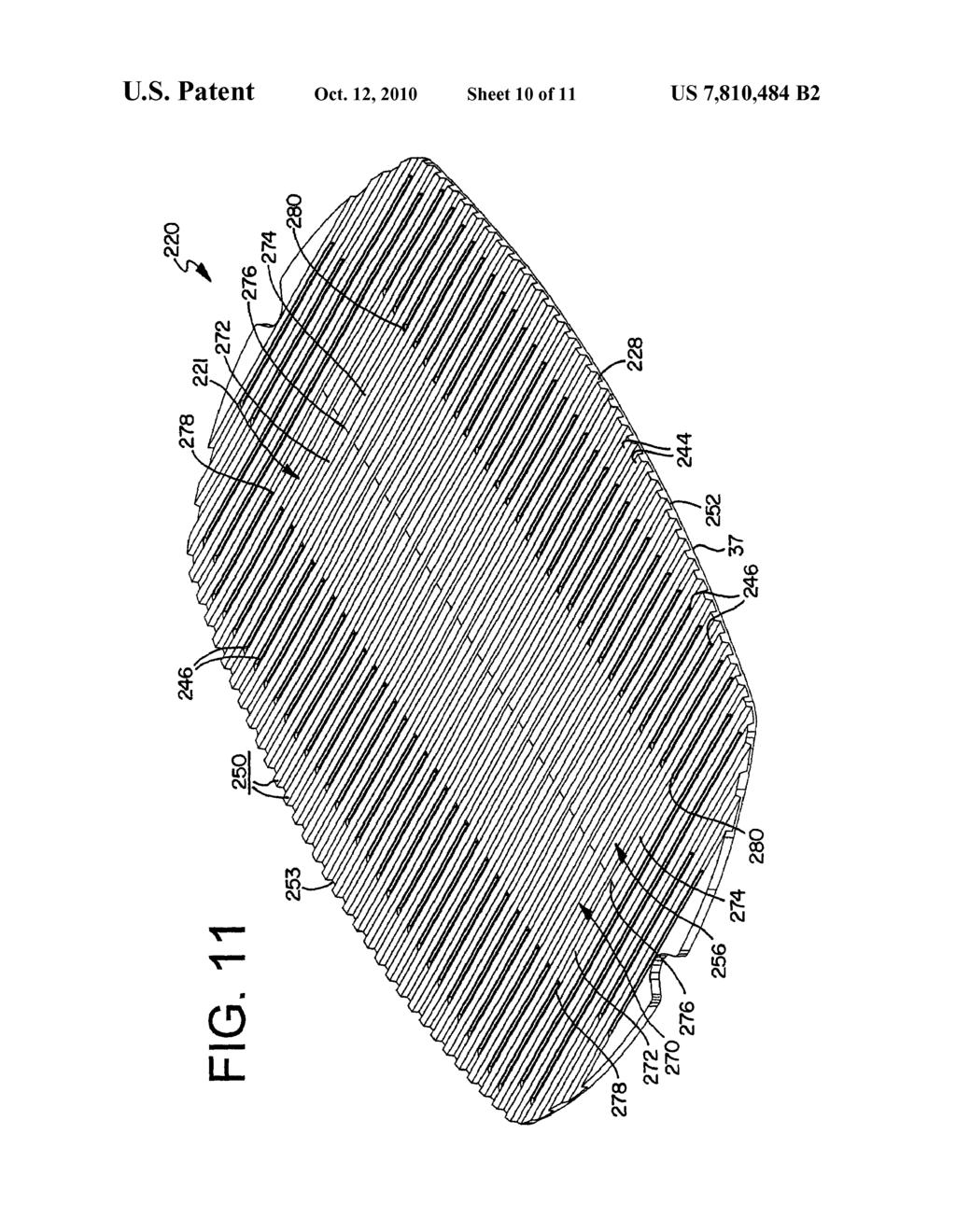
18 distributed substantially evenly throughout the cooking grate 20. This provides for a more even heat distribution and for more uniform cooking. Because the openings 46 only provide approximately 25-30% of the surface area of the total surface area of the grate 20, much of the energy emitted by the burners 32 that is not directed at the energy receptor portions 37 of the grate is maintained in the lower cavity of the grill. Accordingly, since a majority of the energy not consumed by the grate is main tained in the lower cavity of the grill 20, When the lid of the grill is raised a majority of the heat from a barbecue grill employing this type of cooking system does not escape. Fur ther, since the grate 20 is positioned in close proximity to the burners 32, With no structure between the solid energy recep tor portions 37 of the grate 20, the temperature of the grate 20 increases much more quickly than in prior grilling systems. As such, this type of cooking system is much more ef?cient than prior cooking systems. It has been found that this grilling system may be up to approximately 40% to 50% more e?i cient than present cooking systems. Referring to FIGS. 3-6, in a preferred embodiment the grate 20 of the present invention has a grease control assem bly 21 that comprises an upper grease control assembly 56 and a lower grease control assembly 58. The upper grease assembly 56 is generally found on the upper portion of the grate 20. As shown in the?gures, the upper grease assembly 56 generally comprises a sloped grease control surface or structure 72 on an upper surface of the energy receptor por tion 37 of the cooking grate 20. More speci?cally, however, in the preferred embodiment the upper grease control structure comprises two groups, one group for one side of the grate 20 and a second group for a second side of the grate 20. Thus, this grate has a?rst rib group 60, a second rib group 62, a?rst ledge 64, and a second ledge 66. The?rst and second rib groups 60, 62 are longitudinal structures that are positioned between the?rst and second end 41, 43 of the grate 20, and generally extend substantially the length of the grate 20 on the solid energy receptor portions 37. When viewed from above, the?rst and second rib groups 60, 62 have a discontinuous con?guration due to the cooking members 44 that are posi tioned generally perpendicular to the groups 60, 62. The intersection of the?rst rib group 60, the second rib group 62, and the ledges 64, 66 de?nes a central region 68 of the grate 20. As shown in FIG. 3, in this embodiment the central region 68 has a generally rectangular con?guration. The?rst and second rib groups 60, 62 of the upper grease control assembly 56 are comprised of a plurality of ribs 70. Each rib 70 is adapted to direct or guide the How of grease and byproducts generated While cooking food on the grate 20. As shown in FIG. 4, each rib 70 generally has a?rst inclined surface 72 and a second inclined surface 74. The inclined surfaces 72, 74 converge to de?ne a peak or apex 76.Although the peak 76 of the rib 70 is shown positioned below the upper surface 50 of the cooking member 44, the rib 70 can be con?gured such that the peak 76 is coplanar With or above the upper surface 50. The?rst surface 72 has an edge 78 and the second surface 74 has an edge 80, Wherein each edge 78, 80 is adjacent an opening 46. Once grease comes into contact With the rib 70, grease migrates down the inclined surfaces 72, 74 to the edges 78, 80 of the rib 70. In this manner, the drainage of grease and/or byproducts occurs in a controlled and directed manner. The slope or pitch of the inclined sur faces 72, 74 varies With the design parameters of the grease control assembly 21. When viewed from the side, an upper portion of the rib 70 has a generally triangular shape, however, the rib 70 can have a rounded or bulbous con?guration provided that the rib 70 US 7,810,484 B remains adapted to direct the How of grease and byproducts. Alternatively, the rib 70 has only a?rst inclined surface 72 such that the rib 70 has a ramp-like con?guration Wherein the surface 72 extends from the cooking surface 50 towards the side Wall 24, 25 or the bottom Wall 28 of the cooking chamber 18. The?rst inclined surface 72 is oriented to direct the How of grease and byproducts away from or towards the central region 68 of the grate 20. The?rst and second rib groups 60, 62 are positioned about a spine 82 of the grate 20 that gener ally bisects the central region 68. Similar to the?rst and second rib groups 60, 62, the spine 82 has a discontinuous con?guration. As shown in FIG. 5, the spine 82 has a peak 8211 that is preferably positioned below the upper surface 50 of each cooking member 44. Alternatively, the spine 82 is omit ted Wherein the central region 68 has one row of openings 46, and not the two rows of openings 46 as shown in FIG. 3. As discussed above, the grease control assembly 21 com prises a pair of opposed ledges 64, 66. Referring to FIGS. 3-5, each ledge 64, 66 is positioned between the?rst and second rib groups 60, 62 and near a peripheral region of the grate 20. A peripheral set of cooking bars 44aare discontinuous thereby forming intermediate bars 44b. The ledge 64, 66 is proximate the intermediate bars 44b, and thus generally posi tioned at the base of the intermediate bars 44b. Each ledge 64, 66 has a surface 64a, 6611 that is positioned below the upper surface 50 of the cooking members 44. Although the ledge surface 64a, 66a is shown as planar, the surface 64a, 6611 can be inclined or sloped. The?rst ledge 64 has a pair of channels 84 between the cooking bars 44a and the intermediate bars 44b. Alternatively, a single channel 84 is positioned between the peripheral bars 44a thereby eliminating the intermediate bars 44b. The second ledge 66 also has a pair of channels 86 between the cooking bars 44a and the intermediate bars 44b. As shown in FIG. 3, the grate 20 further includes a front external ledge 88 and a rear external ledge 90. The front external ledge 88 is positioned proximate the front edge 52 and the rear external ledge 90 is positioned proximate the rear edge 53. The?rst and second external ledges 88, 90 are discontinuous due to the plurality of cooking bars 44. The?rst and second external ledges 88, 90 extend substantially the length of the grate 20. Preferably, the external ledges 88, 90 are positioned parallel to and below the cooking surface 50. Further, the external ledges 88, 90 are preferably coplanar, however, the external ledges 88, 90 can be inclined to direct the drainage of grease and byproducts generated by cooking food on the grate 20. The Width of the?rst and second external ledges 88, 90 varies along the length of the front and rear edges 52, 53. Referring to FIGS. 3 and 5, the grate 20 further includes a series of lands 92 Wherein each land 92 is posi tioned about the central spine 82 between the intermediate bars 44b and the recess 40, 42. The lands 92 are preferably parallel to the cooking surface 50, however, the lands 92 can be inclined to direct the drainage of grease and cooking byproducts. As discussed above, the grease control assembly 21 of the grate 20 also includes the lower grease control assembly 58. Similar to the upper grease control assembly 56, the lower grease control assembly 58 is adapted to assist in directing the How of grease and byproducts generated by cooking food on the grate 20. Referring to FIGS. 6-7, the lower grease control assembly 58 comprises an outer or?rst ridge 100 that depends from a lower surface 102 of the grate 20, and preferably a lower surface 102 of the solid energy portion 37 of the cook ing grate 20. In a preferred embodiment, the outer ridge 100 has an outer Wall 100a, an inner Wall 100b, and a bottom Wall Each of the Walls 100a, 100b, 1000 have a generally

19 11 smooth surface. The outer ridge 100 has a plurality of linear and curvilinear segments. In addition, the outer ridge 100 has a plurality of protrusions 101. The lower grease control assembly 58 further comprises an inner ridge 104 that depends from the lower surface 102. The inner ridge 104 has an outer Wall 104a, an inner Wall 104b, and a bottom Wall Each of the Walls 104a, 104b, 1040 have a generally smooth surface. Also, the inner ridge 104 has a plurality of linear and curvilinear segments. Preferably, neither the inner ridge 100 nor the outer ridge 104 intersects the openings 46 of the grate 20. The outer and inner ridges 100, 104 depend substantially perpendicular to the lower surface 102 of the grate 102.Altematively, the outer ridge 100 and/ or the inner ridge 104 depend at an angle from the lower surface 102. Referring to FIG. 9, the outer ridge 100 has a height HO, a Width W0, and a perimeter PO. Similarly, the inner ridge 104 has a height H I, a width W,, and a perimeter P I With a generally rectangular con?guration. The outer ridge 100 and the inner ridge 104 de?ne a cavity 106. Like the inner and outer ridges 100, 104, the cavity 106 may have a plurality of linear and curvilinear segments. Pref erably, the cavity 106 does not intersect the openings 46 of the grate 20. The outer and inner ridges 100, 104 are coopera tively positioned With the upper grease control assembly 56. Speci?cally, the outer ridge 100 is cooperatively positioned With the periphery of the?rst and second rib groups 60 and the ledges 64, 66. Also, the inner ridge 104 is cooperatively positioned With the inner bounds of the?rst and second rib groups 60, 62 and the ledges 64, 66. Thus, the cavity 106 is generally positioned between the bounds of the?rst and sec ond rib groups 60, 62 and the ledges 64. As a result, the lower grease control assembly 58 is cooperatively positioned With the upper grease control assembly 56. As shown in FIGS. 1 and 2, When the grate 20 is positioned Within the cooking chamber 12, the grease control assembly 21 is positioned generally above the burner 32. Since the cooking chamber 12 lacks a conventional sear bar or other conductive structure, there is no structure positioned directly between the grate 20 and the burner 32. As explained in greater detail below, the grease control assembly 21 directs and controls the?ow of grease generated by cooking food on the grate 20 in controlled manner such that the grease avoids contact With the burner 32 and exits the cooking chamber 12 through the drain opening 38. As shown in FIG. 8, the grate 20 is positioned Within the cooking chamber 12 to de?ne a use position P1. There, the grate 20 is supported in an elevated position above the burner 32 by engagement between the edges 52, 53 of the grate 20 and the ledge 29 of the?rebox 18. In the use position P1, the grease control assembly 21 is positioned generally above the burner 32. Since the burner 32 of FIGS. 1 and 2 has a loop con?guration, the grease control assembly 21 is positioned above both linear and curvilinear segments of the burner 32. Preferably neither the external ledges 88, 90 nor the openings 46 of the grate 20 are aligned over the burner tube 32. In the use position P1, the lower surface 102 of the grate 20, and speci?cally the lower surface 102 of the solid energy receptor portion 37 of the cooking grate 20 is positioned above the burner tube 32 to de?ne a clearance C. The clear ance C represents the vertical distance between an upper surface of the burner tube 32 and a lower surface of the lower grease control assembly 58 on the solid energy receptor por tion 37 of the cooking grate 20. The amount of the clearance C varies With the design parameters of the grill assembly 10, including the grate 20, the?rebox 18, and the burner tube 32. In the use position P1 of FIG. 8, the outer ridge 100 of the lower grease control assembly 58, and thus the perimeter of US 7,810,484 B the solid energy receptor portion 37 of the cooking grate 20, is generally positioned over an outer portion 32a of the burner tube 32. Speci?cally, as shown in FIG. 10, the outer Wall is positioned beyond the outer portion 32a, the inner Wall 1001) is positioned over the outer portion 32a, and the bottom Wall 1000 is positioned over the outer portion 32a. Described in a different manner, the outer Wall 100a extends beyond the outer Wall 32d of the burner tube 32 such that the outer Wall is not aligned With the outer Wall 32d of the burner tube 32. Accordingly, the surface of the outer Wall 100a de?nes a plane that lies beyond the plane de?ned by the outer Wall 32d of the burner tube 32. Alternatively, the lower grease control assembly 58 is con?gured such that the inner Wall 100!) extends beyond the outer Wall 32d of the burner tube 32. As a result, the surface of the inner Wall 1001) de?nes a plane that lies beyond the plane de?ned by the outer Wall 32d. Additionally, in the use position P1, the inner ridge 104 is generally positioned over an inner portion 32b of the burner tube 32. Speci?cally, the outer Wall is positioned beyond the inner portion 32b, the inner Wall 1041) is positioned over the inner portion 32b, and the bottom Wall 1040 is positioned over the inner portion 32b. Described in a different manner, the outer Wall 104a extends beyond the inner Wall 32e of the burner tube 32 such that the outer Wall is not aligned With the inner Wall 32e of the burner tube 32. Accordingly, the surface of the outer Wall 104a de?nes a plane that lies beyond the plane de?ned by the inner Wall 32e of the burner tube 32. Alternatively, the lower grease control assembly 58 is con?gured such that the inner Wall 1 04b extends beyond the inner Wall 32e of the burner tube 32. As a result, the surface of the inner Wall 1041) de?nes a plane that lies beyond the plane de?ned by the inner Wall 32e. In the use position P1, the cavity 106 is generally posi tioned over an intermediate portion 320 of the burner tube 32, Which contains the outlet ports that a?ame extends from during operation of the barbecue grill assembly 1 0. The cavity 106 is at the bottom surface 102 of the solid energy receptor portion 37 of the cooking grate 20. This means that the cavity 106 below the solid energy receptor portion 37 is generally positioned over the burner?ame region of the burner 32. Preferably, the cavity 106 is cooperatively dimensioned With at least the burner?ame region. Alternatively, the cavity 106 has a con?guration that is substantially similar to the con?gu ration of the burner 32 such that the cavity 106 remains positioned over the burner?ame region. In the event that the cavity 106 is omitted from the lower grease control assembly 58 and there is a generally continuous Wall spanning the inner and outer ridges 100, 104, the outer Walls 100a, 104a remain positioned beyond the outer and inner Walls 32d, 32e of the burner 32. In the use position P1, the upper grease control assembly 56 is positioned on the solid energy receptor portion 37 of the grate 20 and above an extent of the burner tube 32. As shown in FIG. 8, a rib 70 of the?rst rib group 60 is positioned over a portion of the burner tube 32. Similarly, a rib 70 of the second rib group 62 is positioned over a portion of the burner tube 32. In the use position P1 shown in FIG. 10, the?rst surface 72 of the rib 70 is positioned over the intermediate and outer portions 3211, 320 of the burner tube, however, the edge 78 of the?rst surface 72 extends beyond the outer portion 32a. Described in a different manner, the edge 78 extends beyond the outer Wall 32d of the burner tube 32. Further, the second surface 74 of the rib 70 is positioned over the inter mediate and inner portions 32b, 320 of the burner tube 32, however, the edge 80 of the second surface 74 extends beyond the inner portion 32b. Described in a different manner, the edge 80 extends beyond the inner Wall 32e of the burner tube

20 The peak 76 of the rib 70 is positioned generally above the intermediate portion 320 of the burner tube 32. The degree or amount that the edges 78, 80 extend past the Walls of the burner tube 32 varies With the design parameters of the grill assembly 10, including the grate 20, the grease control assem bly 21, and the burner tube 32. FIG. 9 depicts another embodiment of the grate 120 Wherein the grease control assembly 121 has a geometry distinct from that shown in FIG. 8. In this embodiment, the upper grease control assembly 56 of the grease control assem bly 121 has?rst and second rib groups 160, 162 With a unique rib 170 con?guration of the upper surface of the solid energy receptor portion 37 of the grate 20. Speci?cally, the rib 170 has a single inclined surface 172, and not a plurality of inclined surfaces. The inclined surface 172 extends from the cooking surface 50 towards a lower portion of the cooking chamber 18. The inclination of the rib 170 begins at an inter nal edge 178 and terminates at an external edge 180. Alter natively, the inclination of the rib 170 begins at the external edge 180 and terminates at the internal edge 178. The slope or degree of inclination of the rib 170 can vary With the design parameters of the grease control assembly 121, including the design of the?rst rib group 160 and the second rib group 162. In the use position P1, the internal edge 178 generally extends beyond the internal portion 32b and the inner Wall 32e of the burner tube 32, and the external edge 180 generally extends beyond the external portion 32a and the outer Wall 32d of the burner tube 32. During operation of the barbecue grill assembly 10, food is placed on the grate 20 and grease and other byproducts are generated during the cooking process. The quantity of grease and byproducts generated during the cooking process varies With a number of factors, including but not limited to the type of food cooked on the grate 20, the amount of food cooked, the amount of heat generated by the burner tube 32, and the ambient conditions. For example, cooking a steak or ham burger generally more grease and byproducts than an ear of corn or baked potato. Over time and repeated use, grease and byproducts can accumulate and negatively affect the perfor mance and operation of the barbecue grill assembly 10. HoW ever, grease and byproducts are generally?uid such that they?ow or move in a path, primarily due to the effects of gravity. Thus the effective removal of grease and byproducts is an important aspect of the barbecue grill assembly 10. The grate 20 directs and controls the How of grease and byproducts to assist the long-term performance and operation of the barbecue grill assembly 10. Typically, uncooked food is placed on the grate 20 Which may have already been heated by?ames exiting the burner tube 32. As the temperature of the grate 20 and the food increases, grease and other byproducts are generated. Since the food is in direct contact With the grate 20, a measurable quantity of grease comes into contact With various portions of the grate 20. A?rst quantity of the grease comes into contact With at least one opening 46 of the grate 20, and a second quantity of the grease comes into contact With the grease control structure 21 of the grate 20. When the?rst quantity of grease comes into contact With an opening 46, the grease generally?ows through the opening 46 and to the bottom Wall 28 of the?rebox 18 (see FIG. 8). Since the bottom Wall 28 is downwardly sloped, the majority of the grease drains or passes through the drain 38. Because the openings 46 of the grate 20 are not positioned above the burner tube 32, grease that?ows through the openings 46 does not contact the burner tube 32, because the burner tube 32 does not obstruct such?ow. Referring to the schematic view of FIG. 10, grease comes into contact With a portion of the rib 70 and?ows along the rib US 7,810,484 B to de?ne a How path FP Whereby the grease is directed away from contact With the burner tube 32. Typically, grease?rst comes into contact With the?rst inclined surface 72 at an upper portion of the surface 72 near the peak 76. The point Where grease?rst contacts the inclined surface 72 de?nes the beginning or?rst point FP1 of the How path FP. Due to the inclined con?guration of the rib 70, the How path FP of grease continues along the surface 72 until it reaches the edge 78. There, the How path FP experiences a change in direction due to the change in geometry of the rib 70. The point Where the How path FP changes direction occurs proximate the edge 78 and de?nes a second point FP2 of the How path FP. Due to the effects of gravity and the geometry of the rib 70 at the edge 78, a?rst amount of grease in the How path FP loses contact With the rib 70 and this amount of grease passes or drops to the bottom Wall 28 of the?rebox 18. Since the edge 78 extends beyond the outer Wall 32d of the burner tube 32, this amount of grease does not contact the burner 32 as it drains to the bottom Wall 28. Any grease that is on the lower surface 102 of the grate 20 generally traverses until it reaches the outer Wall of the outer ridge 100. There, this grease in the How path FP expe riences a change in direction due to the variation in geometry between the lower surface 102 and the outer ridge 100. The point Where the How path FP changes direction occurs near Where the lower surface 102 meets the outer Wall of the outer ridge 100 and de?nes a third point FP3 of the How path PP. The How path FP of the grease continues along the outer Wall 100a until it reaches the lower edge Where the outer Wall 100a meets the bottom Wall There, due to the effects of gravity and the geometry of the outer Wall 10011, the grease in the flow path PP loses contact With the rib 70 and this amount of grease passes or drops to the bottom Wall 28 of the?rebox 18. The point Where the grease loses contact With the outer Wall 100a de?nes a fourthpoint FP4 of the How path FP. Since the outer Wall of the outer ridge 100 extends beyond the outer Wall 32d of the burner tube 32, grease does not contact the burner tube 32 as it drains to the bottom Wall 28. Thus, the grate 20 provides the How path FP for grease and byproducts generated during the cooking process Whereby the How path FP precludes the grease and byproducts from contacting the burner tube 32. The precise direction of the How path FP is determined by the structural aspects of the grease control assembly 21 of grate 20, including the various components of the upper and lower grease control assemblies 56, 58. Depending on the material utilized to manufacture the cooking grate 20, a protective coating may be applied to the grate 20 to increase the longevity and corrosion resistance of the grate 20. In addition, the protective coating may increase the non-stick properties of the grate 20. In this manner, the protective coating reduces the adhesion between food and the cooking surface 50 of the grate 20. The protective coating is applied to an upper portion of the grate 20, including the cooking member 44 and the upper grease control assembly 56. Also, the protective coating can be applied to the lower grease control assembly 58. The protective coating can be a porcelain coating or another commercially available non stick coating such as a Te?on-based coating. Alternatively, the grate 20 can be plated With nickel or chrome to increase the longevity, corrosion resistance, and/or non-stick proper ties of the grate 20. Further, With certain materials, such as certain cast metals, the plating or coating of the grate 20 may not be necessary. The grate 20 of the present invention can be formed by a number of Ways, including being pressed, cast, or stamped. Further, the grate 20 can be formed in a hybrid manner com bining one or more methods. For example a?rst portion of the
21
22

23
(12) Patent Application Publication (10) Pub. No.: US 2006/ A1
 Patent Application Publication (10) Pub. No.: US 2006/ A1") (19) United States (12) Patent Application Publication (10) Pub. No.: US 2006/0150827 A1 Bruno et al. US 2006O150827A1 (43) Pub. Date: Jul. 13, 2006 (54) (76) (21) (22) (60) GRILLING APPARATUS Inventors:
(19) United States (12) Patent Application Publication (10) Pub. No.: US 2006/0150827 A1 Bruno et al. US 2006O150827A1 (43) Pub. Date: Jul. 13, 2006 (54) (76) (21) (22) (60) GRILLING APPARATUS Inventors:
III. United States Patent (19) Binacchi. Attorney, Agent, or Firm-Bucknam and Archer 57 ABSTRACT. 6 Claims, 3 Drawing Sheets
 Binacchi. Attorney, Agent, or Firm-Bucknam and Archer 57 ABSTRACT. 6 Claims, 3 Drawing Sheets") United States Patent (19) Binacchi 54 APPARATUS FOR MAKING, STARTING FROM A CONTINUOUS FILM, COFFEE ROUND OR NOT ROUND COFFEE WAFERS, FOR ESPRESSO-COFFEE MAKING MACHINES 76 Inventor: Fabio Binacchi, Via
United States Patent (19) Binacchi 54 APPARATUS FOR MAKING, STARTING FROM A CONTINUOUS FILM, COFFEE ROUND OR NOT ROUND COFFEE WAFERS, FOR ESPRESSO-COFFEE MAKING MACHINES 76 Inventor: Fabio Binacchi, Via
(*) Notice: Subject to any disclaimer, the term of this E. E. E. E. O.C.
 Notice: Subject to any disclaimer, the term of this E. E. E. E. O.C.") United States Patent US007021202B2 (12) (10) Patent No.: US 7,021.202 B2 Sizer (45) Date of Patent: Apr. 4, 2006 (54) DISPOSABLE FRYING PAN INSERT 4,828,134 A 5/1989 Ferlanti 5,323,693. A 6/1994 Collard
United States Patent US007021202B2 (12) (10) Patent No.: US 7,021.202 B2 Sizer (45) Date of Patent: Apr. 4, 2006 (54) DISPOSABLE FRYING PAN INSERT 4,828,134 A 5/1989 Ferlanti 5,323,693. A 6/1994 Collard
(12) Patent Application Publication (10) Pub. No.: US 2011/ A1
 Patent Application Publication (10) Pub. No.: US 2011/ A1") US 2011 O174658A1 (19) United States (12) Patent Application Publication (10) Pub. No.: US 2011/0174658 A1 Otsubo (43) Pub. Date: Jul. 21, 2011 (54) DOME LIDS AND CUPS FOR HOT (52) U.S. Cl.... 2O6/508
US 2011 O174658A1 (19) United States (12) Patent Application Publication (10) Pub. No.: US 2011/0174658 A1 Otsubo (43) Pub. Date: Jul. 21, 2011 (54) DOME LIDS AND CUPS FOR HOT (52) U.S. Cl.... 2O6/508
(12) Patent Application Publication (10) Pub. No.: US 2007/ A1
 Patent Application Publication (10) Pub. No.: US 2007/ A1") (19) United States US 20070023463A1 (12) Patent Application Publication (10) Pub. No.: US 2007/0023463 A1 MacClarence (43) Pub. Date: Feb. 1, 2007 (54) REMOVABLE POUR SPOUT (52) U.S. Cl.... 222/567 (76)
(19) United States US 20070023463A1 (12) Patent Application Publication (10) Pub. No.: US 2007/0023463 A1 MacClarence (43) Pub. Date: Feb. 1, 2007 (54) REMOVABLE POUR SPOUT (52) U.S. Cl.... 222/567 (76)
7 IANSNA. (12) Patent Application Publication (10) Pub. No.: US 2003/ A1. (19) United States 2//
 Patent Application Publication (10) Pub. No.: US 2003/ A1. (19) United States 2//") (19) United States US 2003O217647A1 (12) Patent Application Publication (10) Pub. No.: US 2003/0217647 A1 Jones (43) Pub. Date: (54) PORTABLE COOKINGAPPARATUS PROVIDING BOTH DIRECT AND INDIRECT HEAT COOKING
(19) United States US 2003O217647A1 (12) Patent Application Publication (10) Pub. No.: US 2003/0217647 A1 Jones (43) Pub. Date: (54) PORTABLE COOKINGAPPARATUS PROVIDING BOTH DIRECT AND INDIRECT HEAT COOKING
(12) Patent Application Publication (10) Pub. No.: US 2008/ A1
 Patent Application Publication (10) Pub. No.: US 2008/ A1") (19) United States US 20080063772A1 (12) Patent Application Publication (10) Pub. No.: US 2008/0063772 A1 Kirschner et al. (43) Pub. Date: Mar. 13, 2008 (54) CONCENTRATED FRESH BREWED TEA (75) Inventors:
(19) United States US 20080063772A1 (12) Patent Application Publication (10) Pub. No.: US 2008/0063772 A1 Kirschner et al. (43) Pub. Date: Mar. 13, 2008 (54) CONCENTRATED FRESH BREWED TEA (75) Inventors:
(12) Patent Application Publication (10) Pub. No.: US 2005/ A1
 Patent Application Publication (10) Pub. No.: US 2005/ A1") (19) United States US 2005.0089318A1 (12) Patent Application Publication (10) Pub. No.: US 2005/0089318A1 Lai et al. (43) Pub. Date: Apr. 28, 2005 (54) ELECTRIC GRILL (75) Inventors: Wai Hing Lai, Kowloon
(19) United States US 2005.0089318A1 (12) Patent Application Publication (10) Pub. No.: US 2005/0089318A1 Lai et al. (43) Pub. Date: Apr. 28, 2005 (54) ELECTRIC GRILL (75) Inventors: Wai Hing Lai, Kowloon
(12) Patent Application Publication (10) Pub. No.: US 2008/ A1
 Patent Application Publication (10) Pub. No.: US 2008/ A1") (19) United States US 200801 05137A1 (12) Patent Application Publication (10) Pub. No.: US 2008/0105137 A1 Genslak et al. (43) Pub. Date: May 8, 2008 (54) REMOVABLE MOLD FOR A GRILL (76) Inventors: Kristina
(19) United States US 200801 05137A1 (12) Patent Application Publication (10) Pub. No.: US 2008/0105137 A1 Genslak et al. (43) Pub. Date: May 8, 2008 (54) REMOVABLE MOLD FOR A GRILL (76) Inventors: Kristina
US A United States Patent 19 11) Patent Number: 5,607,072 Rigney et al. (45) Date of Patent: Mar. 4, 1997
 Patent Number: 5,607,072 Rigney et al. (45) Date of Patent: Mar. 4, 1997") IIII US005607072A United States Patent 19 11) Patent Number: 5,607,072 Rigney et al. (45) Date of Patent: Mar. 4, 1997 (54) BEVERAGE CONTAINERS 3,759,373 9/1973 Werth et al.... 220/23.4 X 3,948,105 4/1976
IIII US005607072A United States Patent 19 11) Patent Number: 5,607,072 Rigney et al. (45) Date of Patent: Mar. 4, 1997 (54) BEVERAGE CONTAINERS 3,759,373 9/1973 Werth et al.... 220/23.4 X 3,948,105 4/1976
(12) Patent Application Publication (10) Pub. No.: US 2012/ A1
 Patent Application Publication (10) Pub. No.: US 2012/ A1") (19) United States US 20120286O78A1 (12) Patent Application Publication (10) Pub. No.: US 2012/0286078 A1 Bresciani (43) Pub. Date: Nov. 15, 2012 (54) (76) (21) (22) (60) THERMALLY CONTROLLED COFFEE GRINDER
(19) United States US 20120286O78A1 (12) Patent Application Publication (10) Pub. No.: US 2012/0286078 A1 Bresciani (43) Pub. Date: Nov. 15, 2012 (54) (76) (21) (22) (60) THERMALLY CONTROLLED COFFEE GRINDER
(12) Patent Application Publication (10) Pub. No.: US 2012/ A1. Lange (43) Pub. Date: Nov. 22, 2012
 Patent Application Publication (10) Pub. No.: US 2012/ A1. Lange (43) Pub. Date: Nov. 22, 2012") US 20120294997 A1 (19) United States (12) Patent Application Publication (10) Pub. No.: US 2012/0294997 A1 Lange (43) Pub. Date: Nov. 22, 2012 (54) EDIBLE BAKING LINER Publication Classification (51) Int.
US 20120294997 A1 (19) United States (12) Patent Application Publication (10) Pub. No.: US 2012/0294997 A1 Lange (43) Pub. Date: Nov. 22, 2012 (54) EDIBLE BAKING LINER Publication Classification (51) Int.
(12) United States Patent (10) Patent No.: US 6,813,994 B2
 United States Patent (10) Patent No.: US 6,813,994 B2") USOO6813994B2 (12) United States Patent (10) Patent No.: Williams () Date of Patent: Nov. 9, 2004 (54) MULTI-COMPARTMENTED GRIDDLE IRON 3,994.211 11/1976 Stanek 4,3,516 A 8/1982 Sinclair... 99/426 (76)
USOO6813994B2 (12) United States Patent (10) Patent No.: Williams () Date of Patent: Nov. 9, 2004 (54) MULTI-COMPARTMENTED GRIDDLE IRON 3,994.211 11/1976 Stanek 4,3,516 A 8/1982 Sinclair... 99/426 (76)
3,702,608 11/1972 Tibbs. states by bying O st plunger T.
 US006048334A United States Patent (19) 11 Patent Number: Hirschman et al. (45) Date of Patent: Apr. 11, 2000 54 SYRINGE, INJECTOR AND INJECTOR FOREIGN PATENT DOCUMENTS SYSTEM 0064858 A1 11/1982 European
(12) Patent Application Publication (10) Pub. No.: US 2012/ A1
 Patent Application Publication (10) Pub. No.: US 2012/ A1") US 201202.01934A1 (19) United States (12) Patent Application Publication (10) Pub. No.: US 2012/0201934 A1 Youssefi et al. (43) Pub. Date: Aug. 9, 2012 (54) TOPICALLY SEASONEDTACO SHELLS Publication Classification
US 201202.01934A1 (19) United States (12) Patent Application Publication (10) Pub. No.: US 2012/0201934 A1 Youssefi et al. (43) Pub. Date: Aug. 9, 2012 (54) TOPICALLY SEASONEDTACO SHELLS Publication Classification
United States Patent [11] 3,559,565
![United States Patent [11] 3,559,565](/thumbs/93/114425987.jpg "United States Patent [11] 3,559,565") United States Patent [11] 3,559,565 172 21 22 (45) Inventor Clarence A. Getz Hot Springs, Mont. (P.O. Box316 Davenport, Wash. 99122) Appl. No. 810,879 Filed Dec. 24, 1968 Patented Feb.2, 1971 Substitute
United States Patent [11] 3,559,565 172 21 22 (45) Inventor Clarence A. Getz Hot Springs, Mont. (P.O. Box316 Davenport, Wash. 99122) Appl. No. 810,879 Filed Dec. 24, 1968 Patented Feb.2, 1971 Substitute
(12) United States Patent (10) Patent No.: US 7,325,807 B1. Eason (45) Date of Patent: Feb. 5, 2008
 United States Patent (10) Patent No.: US 7,325,807 B1. Eason (45) Date of Patent: Feb. 5, 2008") USOO7325807B1 (12) United States Patent (10) Patent No.: US 7,325,807 B1 Eason (45) Date of Patent: Feb. 5, 2008 (54) BEER PONG TABLE 3,001,791 A 9, 1961 Atwood... 473/470 3,372,934. A * 3/1968 Heil......
USOO7325807B1 (12) United States Patent (10) Patent No.: US 7,325,807 B1 Eason (45) Date of Patent: Feb. 5, 2008 (54) BEER PONG TABLE 3,001,791 A 9, 1961 Atwood... 473/470 3,372,934. A * 3/1968 Heil......
United States Patent (19) 11) 4,167,008 Blickenstaff 45) Sep. 4, 1979
 11) 4,167,008 Blickenstaff 45) Sep. 4, 1979") United States Patent (19) 11) Blickenstaff 45) Sep. 4, 1979 54 FLUID BED CHAFF DESPENSER 75 Inventor: John E. Blickenstaff, North Tonawanda, N.Y. 73) Assignee: Calspan Corporation, Buffalo, N.Y. FOREIGN
United States Patent (19) 11) Blickenstaff 45) Sep. 4, 1979 54 FLUID BED CHAFF DESPENSER 75 Inventor: John E. Blickenstaff, North Tonawanda, N.Y. 73) Assignee: Calspan Corporation, Buffalo, N.Y. FOREIGN
(12) Patent Application Publication (10) Pub. No.: US 2005/ A1
 Patent Application Publication (10) Pub. No.: US 2005/ A1") (19) United States US 2005O260324A1 (12) Patent Application Publication (10) Pub. No.: US 2005/0260324 A1 BOrtolato (43) Pub. Date: (54) AROMATIZED WINE-BASED DRINK (75) Inventor: Massimo Bortolato, Pescantina
(19) United States US 2005O260324A1 (12) Patent Application Publication (10) Pub. No.: US 2005/0260324 A1 BOrtolato (43) Pub. Date: (54) AROMATIZED WINE-BASED DRINK (75) Inventor: Massimo Bortolato, Pescantina
(12) Patent Application Publication (10) Pub. No.: US 2002/ A1
 Patent Application Publication (10) Pub. No.: US 2002/ A1") (19) United States US 20020023912A1 (12) Patent Application Publication (10) Pub. No.: US 2002/0023912 A1 McGee et al. (43) Pub. Date: Feb. 28, 2002 (54) (76) Inventors: Roy McGee, Little Rock, AR (US);
(19) United States US 20020023912A1 (12) Patent Application Publication (10) Pub. No.: US 2002/0023912 A1 McGee et al. (43) Pub. Date: Feb. 28, 2002 (54) (76) Inventors: Roy McGee, Little Rock, AR (US);
United States Patent It 3,593,647
 United States Patent It 3,593,647 72) inventor Walter C. Copeland, Jr. Madison, Fla. 32340 21 Appl. No. 788,369 22 Filed Jan. 2, 1969 45 Patented July 20, 1971 54 BROILER 5 Claims, 8 Drawing Figs. (52)
(12) Patent Application Publication (10) Pub. No.: US 2008/ A1. Hurley et al. (43) Pub. Date: Aug. 28, PROCESS Publication Classification
 Patent Application Publication (10) Pub. No.: US 2008/ A1. Hurley et al. (43) Pub. Date: Aug. 28, PROCESS Publication Classification") US 200802064O9A1 (19) United States (12) Patent Application Publication (10) Pub. No.: US 2008/0206409 A1 Hurley et al. (43) Pub. Date: Aug. 28, 2008 (54) FILLED CONFECTIONARY PRODUCT AND PROCESS (22)
US 200802064O9A1 (19) United States (12) Patent Application Publication (10) Pub. No.: US 2008/0206409 A1 Hurley et al. (43) Pub. Date: Aug. 28, 2008 (54) FILLED CONFECTIONARY PRODUCT AND PROCESS (22)
(12) Patent Application Publication (10) Pub. No.: US 2005/ A1
 Patent Application Publication (10) Pub. No.: US 2005/ A1") (19) United States (12) Patent Application Publication (10) Pub. No.: US 2005/0284884 A1 Roy-Wedderburn US 2005O284884A1 (43) Pub. Date: (54) (76) (21) (22) (60) WINE KIT AND METHOD FOR MAKING WINE Inventor:
(19) United States (12) Patent Application Publication (10) Pub. No.: US 2005/0284884 A1 Roy-Wedderburn US 2005O284884A1 (43) Pub. Date: (54) (76) (21) (22) (60) WINE KIT AND METHOD FOR MAKING WINE Inventor:
(12) Patent Application Publication (10) Pub. No.: US 2013/ A1
 Patent Application Publication (10) Pub. No.: US 2013/ A1") (19) United States US 2013 O149423A1 (12) Patent Application Publication (10) Pub. No.: US 2013/0149423 A1 Lix (43) Pub. Date: Jun. 13, 2013 (54) WHISKEY MAKING METHOD Publication Classification (75) Inventor:
(19) United States US 2013 O149423A1 (12) Patent Application Publication (10) Pub. No.: US 2013/0149423 A1 Lix (43) Pub. Date: Jun. 13, 2013 (54) WHISKEY MAKING METHOD Publication Classification (75) Inventor:
III IIIHIII. United States Patent (19) Momiyama
 Momiyama") United States Patent (19) Momiyama 54 METHOD OF MANUFACTURING INSTANT NOODLESTRP HAVING GOOD RECONSTITUTING PROPERTY 75) Inventor: Yasuo Momiyama. Kashiwa, Japan 73) Assignee: Sanyo Shokuhin Co., Ltd.,
United States Patent (19) Momiyama 54 METHOD OF MANUFACTURING INSTANT NOODLESTRP HAVING GOOD RECONSTITUTING PROPERTY 75) Inventor: Yasuo Momiyama. Kashiwa, Japan 73) Assignee: Sanyo Shokuhin Co., Ltd.,
United States Patent (19) 11 Patent Number: 5,323,693 Collard et al. (45) Date of Patent: Jun. 28, 1994
 11 Patent Number: 5,323,693 Collard et al. (45) Date of Patent: Jun. 28, 1994") III US00532.3693A United States Patent (19) 11 Patent Number: 5,323,693 Collard et al. (45) Date of Patent: Jun. 28, 1994 (54) COMBINATION FRYING PAN INSERT AND 3,469,524 9/1969 FRYING PAN 3,837,330 9/1974
III US00532.3693A United States Patent (19) 11 Patent Number: 5,323,693 Collard et al. (45) Date of Patent: Jun. 28, 1994 (54) COMBINATION FRYING PAN INSERT AND 3,469,524 9/1969 FRYING PAN 3,837,330 9/1974
(12) Patent Application Publication (10) Pub. No.: US 2003/ A1
 Patent Application Publication (10) Pub. No.: US 2003/ A1") US 20030003199A1 (19) United States (12) Patent Application Publication (10) Pub. No.: US 2003/0003199 A1 Perez (43) Pub. Date: Jan. 2, 2003 (54) METHOD AND APPARATUS FOR Publication Classification UTILIZING
US 20030003199A1 (19) United States (12) Patent Application Publication (10) Pub. No.: US 2003/0003199 A1 Perez (43) Pub. Date: Jan. 2, 2003 (54) METHOD AND APPARATUS FOR Publication Classification UTILIZING
Sept. 7, l.t. ward 2,092,596 SIPHON
 Sept. 7, 1937. l.t. ward SIPHON Filed Aug., 1936 3 Sheets-Sheet 1 NVENOR 4 weawea 7 Aead. Sept. 7, 1937. Lt. WARD SIPHON Filed Aug., 1936 3. Sheets-Sheet 2 N.VENOR 44 pea Mca 7 A2aa. Sept. 7, 1937. L.
Table of Contents. Foundation and Preparation 2 Hearth Base Dimensions 2. Laying the Inner Hearth 3 Inner Hearth Dimensions 4
 Table of Contents Foundation and Preparation 2 Hearth Base Dimensions 2 Laying the Inner Hearth 3 Inner Hearth Dimensions 4 Constructing the Firebox 5 Face Opening Dimensions 5 Setting the Rumford Throat
United States Patent (19) Bowen et al.
 Bowen et al.") United States Patent (19) Bowen et al. 11) Patent Number: 5,004,617 45 Date of Patent: Apr. 2, 1991 54 (75) (73) 21 22) 62 (51) 52) (58) METHOD OF HEATING FOOD Inventors: Assignee: Appl. No.: 448,408 Robert
United States Patent (19) Bowen et al. 11) Patent Number: 5,004,617 45 Date of Patent: Apr. 2, 1991 54 (75) (73) 21 22) 62 (51) 52) (58) METHOD OF HEATING FOOD Inventors: Assignee: Appl. No.: 448,408 Robert
United States Patent (19)
") United States Patent (19) Traeger et al. (54) (76) (21) 22 (51) (52) (58 (56) PELLET-FIRED BARBEGUE Inventors: Joseph P. Traeger, 250 S. Oak St.; Randolph J. Traeger, 530 Alder St.; Mark A. Traeger, 540
United States Patent (19) Traeger et al. (54) (76) (21) 22 (51) (52) (58 (56) PELLET-FIRED BARBEGUE Inventors: Joseph P. Traeger, 250 S. Oak St.; Randolph J. Traeger, 530 Alder St.; Mark A. Traeger, 540
March 24, 1970 H. H. BRIDGFORD 3,502,488 COMBINED FROZEN DOUGH PACKAGE AND BAKING CONTAINER HUGH. BROGFORD / ATTORNEY
 March 24, 1970 H. H. BRIDGFORD COMBINED FROZEN DOUGH PACKAGE AND BAKING CONTAINER Filed July 25, 1968 3. Sheets-Sheet HUGH. BROGFORD /4-4-6-4 ATTORNEY March 24, 1970 H. H. BRIDGFord COMBINED FROZEN DOUGH
3. : 12- C) {X C> C) () {X -K) --KX-KX-KX-K)--C-2 --C)-- (12) Patent Application Publication (10) Pub. No.: US 2012/ A1 4 - (19) United States
 {X C> C) () {X -K) --KX-KX-KX-K)--C-2 --C)-- (12) Patent Application Publication (10) Pub. No.: US 2012/ A1 4 - (19) United States") (19) United States US 2012O138603A1 (12) Patent Application Publication (10) Pub. No.: US 2012/0138603 A1 McGuinness et al. (43) Pub. Date: Jun. 7, 2012 (54) VARIABLE GEOMETRY TORTILLA COOKINGAPPARATUS
(19) United States US 2012O138603A1 (12) Patent Application Publication (10) Pub. No.: US 2012/0138603 A1 McGuinness et al. (43) Pub. Date: Jun. 7, 2012 (54) VARIABLE GEOMETRY TORTILLA COOKINGAPPARATUS
United States Patent (19) D'Alessandro
 D'Alessandro") United States Patent (19) D'Alessandro 54 (76) 21) 22 (51) 52 (58) (56) WOOD BURNINGSTOVE AND OVEN Inventor: Sebastiano D'Alessandro, 74 Knockbolt Crescent, Scarborough, Ontario M1S2P6, Canada Appl. No.:
United States Patent (19) D'Alessandro 54 (76) 21) 22 (51) 52 (58) (56) WOOD BURNINGSTOVE AND OVEN Inventor: Sebastiano D'Alessandro, 74 Knockbolt Crescent, Scarborough, Ontario M1S2P6, Canada Appl. No.:
May 12, ,282,708 T. DANTZIG COFFEE ROASTING PRODUCT, METHOD, AND MACHINE. Filed Sept. 26, Sheets-Sheet l. --No.zzzzzzzzzzae.
 May 12, 1942. T. DANTZIG COFFEE ROASTING PRODUCT, METHOD, AND MACHINE Filed Sept. 26, 1940 2,282,708 2. Sheets-Sheet l --No.zzzzzzzzzzae zs ZzZ2 May 12, 1942. T. DANTZIG 2,282,708 COFFEE ROASTING PRODUCT,
United States Patent (19) Forino
 Forino") United States Patent (19) Forino (54) 76) 21 22 (51) (52) (58) 56) METHOD FOR MAKING FERMENTED BEVERAGES Inventor: Vincent Forino, 2922 E. Main St., Waterbury, Conn. 06705 Appl. No.: 204,888 Filed: Jun
United States Patent (19) Forino (54) 76) 21 22 (51) (52) (58) 56) METHOD FOR MAKING FERMENTED BEVERAGES Inventor: Vincent Forino, 2922 E. Main St., Waterbury, Conn. 06705 Appl. No.: 204,888 Filed: Jun
(12) United States Patent
 United States Patent") USOO945 1844B2 (12) United States Patent Olucha Soler et al. (10) Patent No.: (45) Date of Patent: US 9.451,844 B2 Sep. 27, 2016 (54) DEVICE FOR DIRECTLY OBTAINING JUICE FROM FRUIT (75) Inventors: Jordi
USOO945 1844B2 (12) United States Patent Olucha Soler et al. (10) Patent No.: (45) Date of Patent: US 9.451,844 B2 Sep. 27, 2016 (54) DEVICE FOR DIRECTLY OBTAINING JUICE FROM FRUIT (75) Inventors: Jordi
(12) United States Patent
 United States Patent") (12) United States Patent Song-Bodenstab et al. USOO654.1056B1 (10) Patent No.: (45) Date of Patent: Apr. 1, 2003 (54) MALTED BEVERAGE POWDER AND PROCESS (75) Inventors: Xiaomei Song-Bodenstab, Mannens
(12) United States Patent Song-Bodenstab et al. USOO654.1056B1 (10) Patent No.: (45) Date of Patent: Apr. 1, 2003 (54) MALTED BEVERAGE POWDER AND PROCESS (75) Inventors: Xiaomei Song-Bodenstab, Mannens
United States Patent (19)
") United States Patent (19) Hawley 54 METHOD OF FORMING A PACKAGED EGG PRODUCT 75 linventor: Robert Lyle Hawley, Webster Groves, Mo. 73) Assignee: Ralston Purina Company, St. Louis, Mo. 22 Filed: July 23,
United States Patent (19) Hawley 54 METHOD OF FORMING A PACKAGED EGG PRODUCT 75 linventor: Robert Lyle Hawley, Webster Groves, Mo. 73) Assignee: Ralston Purina Company, St. Louis, Mo. 22 Filed: July 23,
(12) Patent Application Publication (10) Pub. No.: US 2008/ A1
 Patent Application Publication (10) Pub. No.: US 2008/ A1") (19) United States US 20080216664A1 (12) Patent Application Publication (10) Pub. No.: US 2008/0216664 A1 K00n et al. (43) Pub. Date: Sep. 11, 2008 (54) ELECTRONICTEATHERMOMETER AND TIMER DEVICE (75) Inventors:
(19) United States US 20080216664A1 (12) Patent Application Publication (10) Pub. No.: US 2008/0216664 A1 K00n et al. (43) Pub. Date: Sep. 11, 2008 (54) ELECTRONICTEATHERMOMETER AND TIMER DEVICE (75) Inventors:
III. United States Patent (19) 5,590,586 Jan. 7, % 4. Ulfig et al. (75) Inventors: Kimberly A. Ulfig, Glen Ellyn;
 5,590,586 Jan. 7, % 4. Ulfig et al. (75) Inventors: Kimberly A. Ulfig, Glen Ellyn;") United States Patent (19) Ulfig et al. 54 KITCHEN LAYOUT, SYSTEM (75) Inventors: Kimberly A. Ulfig, Glen Ellyn; Patricia A. Venetucci, Hawthorn Woods, both of Ill. (73) Assignee: Restaurant Technology,
United States Patent (19) Ulfig et al. 54 KITCHEN LAYOUT, SYSTEM (75) Inventors: Kimberly A. Ulfig, Glen Ellyn; Patricia A. Venetucci, Hawthorn Woods, both of Ill. (73) Assignee: Restaurant Technology,
United States Patent (19) Ludder
 Ludder") United States Patent (19) Ludder (54) CLOSE-NESTING, LIGHT-WEIGHT, ONE-PECE DRINKING CUP AND APPARATUS FOR THE MANUFACTURE THEREOF (75) Inventor: Rodney E. Ludder, Glen Head, N.Y. 73) Assignee: Owens-Illinois,
United States Patent (19) Ludder (54) CLOSE-NESTING, LIGHT-WEIGHT, ONE-PECE DRINKING CUP AND APPARATUS FOR THE MANUFACTURE THEREOF (75) Inventor: Rodney E. Ludder, Glen Head, N.Y. 73) Assignee: Owens-Illinois,
Dec. 9, M. H. SMITH 2,265,550
 Dec. 9, 1941. M. H. SMITH 2,265,550 STRAINER Filed July 3, 1940. 2 Sheets-Sheet l %rk --L-A- NYA 2 43 N yzes N S/2 Su2 S %zzzzzzzzzzzo Nventor MYRON -, SMITH Aftorneys Dec. 9, 1941.. M. H. SMITH 2,265,550
(12) United States Patent (10) Patent No.: US 6,419,120 B1
 United States Patent (10) Patent No.: US 6,419,120 B1") USOO641912OB1 (12) United States Patent (10) Patent No.: BertOne (45) Date of Patent: Jul. 16, 2002 (54) MULTI-FLAVORED HOT BEVERAGE 6,202,894 B1 * 3/2001 Struminski et al.... 222/129.3 DSPENSER * cited
USOO641912OB1 (12) United States Patent (10) Patent No.: BertOne (45) Date of Patent: Jul. 16, 2002 (54) MULTI-FLAVORED HOT BEVERAGE 6,202,894 B1 * 3/2001 Struminski et al.... 222/129.3 DSPENSER * cited
(54) POPCORN BUTTER DISPENSER Publication Classi?cation
 POPCORN BUTTER DISPENSER Publication Classi?cation") US 20140054316A1 (19) United States (12) Patent Application Publication (10) Pub. No.: US 2014/0054316 A1 Lehman et al. (43) Pub. Date: Feb. 27, 2014 (54) POPCORN BUTTER DISPENSER Publication Classi?cation
US 20140054316A1 (19) United States (12) Patent Application Publication (10) Pub. No.: US 2014/0054316 A1 Lehman et al. (43) Pub. Date: Feb. 27, 2014 (54) POPCORN BUTTER DISPENSER Publication Classi?cation
United States Patent (19)
") United States Patent (19) Hayashi (54) BIOCHEMICAL REACTION ANALYZING APPARATUS 75 Inventor: Hidechika Hayashi, Yokohama, Japan 73 Assignee: Tosoh Corporation, Shinnanyo, Japan (21) Appl. No.: 503,109
United States Patent (19) Hayashi (54) BIOCHEMICAL REACTION ANALYZING APPARATUS 75 Inventor: Hidechika Hayashi, Yokohama, Japan 73 Assignee: Tosoh Corporation, Shinnanyo, Japan (21) Appl. No.: 503,109
Grooving Tool: used to cut the soil in the liquid limit device cup and conforming to the critical dimensions shown in AASHTO T 89 Figure 1.
 DETERMINING THE LIQUID LIMIT OF SOILS FOP FOR AASHTO T 89 Scope This procedure covers the determination of the liquid limit of a soil in accordance with AASHTO T 89-13. It is used in conjunction with the
United States Patent (19) Best
 Best") United States Patent (19) Best 54 INFRARED GAS GRILL 76 Inventor: Willie H. Best, 18C The Heritage, Columbia, S.C. 29201 (21) Appl. No.: 138,854 22 Filed: Apr. 8, 1980 51) Int. C.... A47J 37/04 52 U.S.C....
United States Patent (19) Best 54 INFRARED GAS GRILL 76 Inventor: Willie H. Best, 18C The Heritage, Columbia, S.C. 29201 (21) Appl. No.: 138,854 22 Filed: Apr. 8, 1980 51) Int. C.... A47J 37/04 52 U.S.C....
(12) United States Patent
 United States Patent") (12) United States Patent USOO8469225B2 () Patent No.: US 8,469.225 B2 Fredland (45) Date of Patent: Jun. 25, 2013 (54) SEMI-RIGID BEVERAGE RECEPTACLE (56) References Cited (75) Inventor: Richard Fredland,
(12) United States Patent USOO8469225B2 () Patent No.: US 8,469.225 B2 Fredland (45) Date of Patent: Jun. 25, 2013 (54) SEMI-RIGID BEVERAGE RECEPTACLE (56) References Cited (75) Inventor: Richard Fredland,
Center et al. (45. Date of Patent: Aug. 29, 1995
 United States Patent (19) 11 USOO5445287A Patent Number: 5,445,287 Center et al. (45. Date of Patent: Aug. 29, 1995 54 CO-DISPENSING SNACK FOOD PRODUCTS 5,176,287 1/1993 Suris AND BEVERAGES FROM A VENDING
(12) Patent Application Publication (10) Pub. No.: US 2017/ A1
 Patent Application Publication (10) Pub. No.: US 2017/ A1") (19) United States US 2017.0089590A1 (12) Patent Application Publication (10) Pub. No.: US 2017/0089590 A1 Bruin-Slot et al. (43) Pub. Date: Mar. 30, 2017 (54) OVEN CAVITY CONNECTOR FOR (52) U.S. Cl. OPERATING
(19) United States US 2017.0089590A1 (12) Patent Application Publication (10) Pub. No.: US 2017/0089590 A1 Bruin-Slot et al. (43) Pub. Date: Mar. 30, 2017 (54) OVEN CAVITY CONNECTOR FOR (52) U.S. Cl. OPERATING
Sugar maple tree named Legacy
 ( 1 of 1 ) United States Patent PP4,979 Wandell February 1, 1983 Sugar maple tree named Legacy Abstract This disclosure concerns a new and distinct variety of Acer saccharum (commonly known as sugar maple
(12) Patent Application Publication (10) Pub. No.: US 2012/ A1
 Patent Application Publication (10) Pub. No.: US 2012/ A1") (19) United States US 20120279416A1 (12) Patent Application Publication (10) Pub. No.: US 2012/0279416A1 Nishimura et al. (43) Pub. Date: Nov. 8, 2012 (54) RAILCAR BOGIE (52) U.S. Cl.... 105/218.1 (75)
(19) United States US 20120279416A1 (12) Patent Application Publication (10) Pub. No.: US 2012/0279416A1 Nishimura et al. (43) Pub. Date: Nov. 8, 2012 (54) RAILCAR BOGIE (52) U.S. Cl.... 105/218.1 (75)
(12) Patent Application Publication (10) Pub. No.: US 2007/ A1
 Patent Application Publication (10) Pub. No.: US 2007/ A1") US 20070178190A1 (19) United States (12) Patent Application Publication (10) Pub. No.: US 2007/0178190 A1 Vatelot (43) Pub. Date: Aug. 2, 2007 (54) GRAPE TREATMENT METHOD FOR WINE (30) Foreign Application
US 20070178190A1 (19) United States (12) Patent Application Publication (10) Pub. No.: US 2007/0178190 A1 Vatelot (43) Pub. Date: Aug. 2, 2007 (54) GRAPE TREATMENT METHOD FOR WINE (30) Foreign Application
(12) Plant Patent Application Publication
 Plant Patent Application Publication") (19) United States (12) Plant Patent Application Publication Martin US 20100 199395P1 (10) Pub. No.: (43) Pub. Date: Aug. 5, 2010 (54) BRUGMANSIA ANGELS SUMMER DREAM (76) Inventor: Byron E. Martin, Danielson,
(19) United States (12) Plant Patent Application Publication Martin US 20100 199395P1 (10) Pub. No.: (43) Pub. Date: Aug. 5, 2010 (54) BRUGMANSIA ANGELS SUMMER DREAM (76) Inventor: Byron E. Martin, Danielson,
3,000 POUND CAPACITY AUTO BODY ROTISSERIE UNIT
 3,000 POUND CAPACITY AUTO BODY ROTISSERIE UNIT INSTALLATION / OWNERS MANUAL ROTISSERIE (R3000G) 1 IN50016 Rev. B 03/30/2009 TABLE OF CONTENTS IMPORTANT INFORMATION...pg 2 OWNER / EMPLOYER RESPONSIBILITIES...pg
(12) United States Patent
 United States Patent") US007582325B2 (12) United States Patent Giori () Patent No.: (45) Date of Patent: Sep. 1, 2009 (54) PROCESS FOR THE PREPARATION OF TOMATO EXTRACTS WITH HIGH CONTENT IN LYCOPENE (75) Inventor: Andrea Giori,
US007582325B2 (12) United States Patent Giori () Patent No.: (45) Date of Patent: Sep. 1, 2009 (54) PROCESS FOR THE PREPARATION OF TOMATO EXTRACTS WITH HIGH CONTENT IN LYCOPENE (75) Inventor: Andrea Giori,
(12) Patent Application Publication (10) Pub. No.: US 2004/ A1
 Patent Application Publication (10) Pub. No.: US 2004/ A1") (19) United States (12) Patent Application Publication (10) Pub. No.: US 2004/0187694 A1 Cai US 2004O187694A1 (43) Pub. Date: (54) (76) (21) (22) (63) HOLDER FOR PRESSURE-BREWING COFFEE DRINK Inventor:
(19) United States (12) Patent Application Publication (10) Pub. No.: US 2004/0187694 A1 Cai US 2004O187694A1 (43) Pub. Date: (54) (76) (21) (22) (63) HOLDER FOR PRESSURE-BREWING COFFEE DRINK Inventor:
(12) Patent Application Publication (10) Pub. No.: US 2004/ A1
 Patent Application Publication (10) Pub. No.: US 2004/ A1") US 2004OO16772A1 (19) United States (12) Patent Application Publication (10) Pub. No.: US 2004/0016772 A1 Rupp (43) Pub. Date: Jan. 29, 2004 (54) FLAVOR DISPENSING DEVICE Publication Classification (76)
US 2004OO16772A1 (19) United States (12) Patent Application Publication (10) Pub. No.: US 2004/0016772 A1 Rupp (43) Pub. Date: Jan. 29, 2004 (54) FLAVOR DISPENSING DEVICE Publication Classification (76)
INTRODUCTION. Your new smoker comes almost completely assembled. You will need to complete the assembly which includes:
 INTRODUCTION Congratulations on your purchase of this Smith & Wesson SMOKER, Model SWS032. With proper set-up, operation and maintenance, this smoker will provide you with years of cooking enjoyment. Your
(12) United States Patent (10) Patent No.: US 8,601,937 B2
 United States Patent (10) Patent No.: US 8,601,937 B2") USOO8601937B2 (12) United States Patent () Patent No.: Campetella et al. (45) Date of Patent: Dec., 2013 (54) APPARATUS FOR MAKING COFFEE 5,605,091 A * 2/1997 Garber... 99,330 5,650,186 A * 7/1997 Annoni
USOO8601937B2 (12) United States Patent () Patent No.: Campetella et al. (45) Date of Patent: Dec., 2013 (54) APPARATUS FOR MAKING COFFEE 5,605,091 A * 2/1997 Garber... 99,330 5,650,186 A * 7/1997 Annoni
(12) United States Patent
 United States Patent") (12) United States Patent Mueller USOO6942888B2 (10) Patent No.: (45) Date of Patent: Sep. 13, 2005 (54) CHEESE EXTRUDING MACHINE AND PROCESS FOR PRODUCING PIECES OF CHEESE (75) Inventor: Adam P. Mueller,
(12) United States Patent Mueller USOO6942888B2 (10) Patent No.: (45) Date of Patent: Sep. 13, 2005 (54) CHEESE EXTRUDING MACHINE AND PROCESS FOR PRODUCING PIECES OF CHEESE (75) Inventor: Adam P. Mueller,
Beer Hardware, Systems and Delivery
 Beer Hardware, Systems and Delivery An Industry Standard Beer is the number one dispensed beverage in the foodservice industry. Commonly, draft beer is preferred by a wide margin for taste and product
(12) Unlted States Patent (10) Patent N0.2 US 7,611,743 B2 Laye et al. (45) Date of Patent: Nov. 3, 2009
 Unlted States Patent (10) Patent N0.2 US 7,611,743 B2 Laye et al. (45) Date of Patent: Nov. 3, 2009") US007611743B2 (12) Unlted States Patent (10) Patent N0.2 Laye et al. () Date of Patent: Nov. 3, 09 (54) LOW PROTEIN CREAM CHEESE 4,749,584 A 6/ 1988 Wirchansky et a1. 5,079,024 A 1/1992 Crane (75) Inventors:
US007611743B2 (12) Unlted States Patent (10) Patent N0.2 Laye et al. () Date of Patent: Nov. 3, 09 (54) LOW PROTEIN CREAM CHEESE 4,749,584 A 6/ 1988 Wirchansky et a1. 5,079,024 A 1/1992 Crane (75) Inventors:
(12) Patent Application Publication (10) Pub. No.: US 2013/ A1
 Patent Application Publication (10) Pub. No.: US 2013/ A1") (19) United States (12) Patent Application Publication (10) Pub. No.: US 2013/0017300 A1 Avila et al. US 2013 001.7300A1 (43) Pub. Date: (54) (75) (73) (21) (22) (60) METHOD OF PREPARING AN OATCONTAINING
(19) United States (12) Patent Application Publication (10) Pub. No.: US 2013/0017300 A1 Avila et al. US 2013 001.7300A1 (43) Pub. Date: (54) (75) (73) (21) (22) (60) METHOD OF PREPARING AN OATCONTAINING
(12) Patent Application Publication (10) Pub. No.: US 2017/ A1
 Patent Application Publication (10) Pub. No.: US 2017/ A1") US 201700 13866A1 (19) United States (12) Patent Application Publication (10) Pub. No.: US 2017/0013866A1 Tanaka et al. (43) Pub. Date: (54) EXTRUDED NOODLE AND DIE PIECE FOR (30) Foreign Application Priority
US 201700 13866A1 (19) United States (12) Patent Application Publication (10) Pub. No.: US 2017/0013866A1 Tanaka et al. (43) Pub. Date: (54) EXTRUDED NOODLE AND DIE PIECE FOR (30) Foreign Application Priority
(12) United States Patent
 United States Patent") (12) United States Patent Chapman et al. USOO6539842B1 (10) Patent No.: (45) Date of Patent: US 6,539,842 B1 Apr. 1, 2003 (54) (75) (73) (21) (22) (51) (52) (58) (56) ROTISSERIE SYSTEM HAVING AREMOTE TEMPERATURE
(12) United States Patent Chapman et al. USOO6539842B1 (10) Patent No.: (45) Date of Patent: US 6,539,842 B1 Apr. 1, 2003 (54) (75) (73) (21) (22) (51) (52) (58) (56) ROTISSERIE SYSTEM HAVING AREMOTE TEMPERATURE
(12) Plant Patent Application Publication
 Plant Patent Application Publication") (19) United States (12) Plant Patent Application Publication Pate US 201001.38965P1 (10) Pub. No.: US 2010/0138965 P1 (43) Pub. Date: Jun. 3, 2010 (54) BLUEBERRY VARIETY NAMED BLUE MOON (75) Inventor:
(19) United States (12) Plant Patent Application Publication Pate US 201001.38965P1 (10) Pub. No.: US 2010/0138965 P1 (43) Pub. Date: Jun. 3, 2010 (54) BLUEBERRY VARIETY NAMED BLUE MOON (75) Inventor:
United States Patent (19) Kovacevich, Jr.
 Kovacevich, Jr.") United States Patent (19) Kovacevich, Jr. 11 Patent Number: Date of Patent: Jun. 9, 1987 54) 76 21 22 63 (51) 52 58 56) WNE DISTRIBUTION METHOD Inventor: Appl. No.: Filed: Sam Kovacevich, Jr., R.R. 1,
United States Patent (19) Kovacevich, Jr. 11 Patent Number: Date of Patent: Jun. 9, 1987 54) 76 21 22 63 (51) 52 58 56) WNE DISTRIBUTION METHOD Inventor: Appl. No.: Filed: Sam Kovacevich, Jr., R.R. 1,
JUICE EXTRACTION AND FILTRATION JUICE EXTRACTION METHOD AND EQUIPMENT
 College of Agricultural Engineering and Technology Dept. of Agricultural Processing and Food Engineering Course : Dairy and Food Engineering Chapter 11 JUICE EXTRACTION AND FILTRATION (Juice extraction
STEAM TUBES OVENS RANGE
 STEAM TUBES OVENS RANGE 1 Steam tube deck oven PRIME KAPPA FOKUS MINI STAR STONE MINI STAR RING Multi deck steam tube oven TOWER 2 Steam tube ovens PRIME - KAPPA(Stone heating system) LoGiudice Forni is
KAMADO JOE GASJOE THE NEXT REVOLUTION IN GRILLING. Shown: GasJoe 38. GasJoe Specifications
 THE NEXT REVOLUTION IN GRILLING Shown: GasJoe 38 GasJoe Specifications 26 FEATURES & SPECIFICATIONS Includes: Grill Head & Cart Grill Head and Cart Ship Separately. Cart Comes Fully Assembled. Grill Head
(12) Patent Application Publication (10) Pub. No.: US 2010/ A1
 Patent Application Publication (10) Pub. No.: US 2010/ A1") (19) United States US 2010.0005979A1 (12) Patent Application Publication (10) Pub. No.: US 2010/0005979 A1 Baccetti (43) Pub. Date: Jan. 14, 2010 (54) DISPOSABLE BEVERAGE PRESS Publication Classification
(19) United States US 2010.0005979A1 (12) Patent Application Publication (10) Pub. No.: US 2010/0005979 A1 Baccetti (43) Pub. Date: Jan. 14, 2010 (54) DISPOSABLE BEVERAGE PRESS Publication Classification
PATENT ATTORNEYS EXAMINATION
 2014 PATENT ATTORNEYS EXAMINATION PAPER E The New Zealand Law and Practice relating to Interpretation and Criticism of Patent Specifications Regulation 158 (1) (e) Duration: 4 hours (plus 10 minutes for
KAMADO JOE GASJOE ULTRA
 THE NEXT REVOLUTION IN GRILLING Shown: GasJoe Ultra 42 GasJoe Ultra Specifications 30 FEATURES & SPECIFICATIONS Includes: Grill Head & Cart Grill Head and Cart Ship Separately. Cart Comes Fully Assembled.
INTRODUCTION TO CUSTOM FABRICATED STRAINERS
 INTRODUCTION TO CUSTOM FABRICATED STRAINERS Nothing Too Big, Too Small or Too Special When unwanted solid material has to be removed from flowing fluids in order to protect equipment, a HAYWARD Strainer
INFRARED BURNER KIT INSTRUCTIONS
 3 INFRARED BURNER KIT INSTRUCTIONS (HOT SURFACE IGNITION) 5 1 4 NOTE: This unit has been retrofi tted with an infrared burner. Model # 3050 # 3060 Included parts 2 6* PARTS INCLUDED 1. Infrared burner
SIMPLEX STRAINER MODEL 90
 The Eaton Model 90 Fabricated Simplex Strainer has been designed for manufacturing flexibility. It can be made for pipeline sizes from 1 to 48 in carbon steel or stainless steel although other materials
(12) Ulllted States Patent (10) Patent N0.: US 7,560,129 B2 Mehnert et al. (45) Date of Patent: Jul. 14, 2009
 Ulllted States Patent (10) Patent N0.: US 7,560,129 B2 Mehnert et al. (45) Date of Patent: Jul. 14, 2009") US00756029B2 (2) Ulllted States Patent (0) Patent N0.: Mehnert et al. (45) Date of Patent: Jul. 4, 2009 (54) MANUFACTURE OF LARGE CHEESE 3,404,009 A 0/968 Lambert et a. BLOCKS HAVING REDUCED MOISTURE 4,049,838
US00756029B2 (2) Ulllted States Patent (0) Patent N0.: Mehnert et al. (45) Date of Patent: Jul. 4, 2009 (54) MANUFACTURE OF LARGE CHEESE 3,404,009 A 0/968 Lambert et a. BLOCKS HAVING REDUCED MOISTURE 4,049,838
1. IMPORTANT SAFEGUARDS When using electrical appliances, basic safety precautions should always be followed to reduce the risk of fire, electric
 1. IMPORTANT SAFEGUARDS When using electrical appliances, basic safety precautions should always be followed to reduce the risk of fire, electric shock, and/pr injury to persons including the following:
(12) Patent Application Publication (10) Pub. No.: US 2004/ A1
 Patent Application Publication (10) Pub. No.: US 2004/ A1") (19) United States US 20040O866O1A1 (12) Patent Application Publication (10) Pub. No.: US 2004/0086601A1 ROSS et al. (43) Pub. Date: (54) SCORED SAVORY DOUGH WITH TOPPINGS OR FILLINGS (76) Inventors: Robert
(19) United States US 20040O866O1A1 (12) Patent Application Publication (10) Pub. No.: US 2004/0086601A1 ROSS et al. (43) Pub. Date: (54) SCORED SAVORY DOUGH WITH TOPPINGS OR FILLINGS (76) Inventors: Robert
(12) Patent Application Publication (10) Pub. No.: US 2004/ A1
 Patent Application Publication (10) Pub. No.: US 2004/ A1") US 2004O241299A1 (19) United States (12) Patent Application Publication (10) Pub. No.: US 2004/0241299 A1 Zhang (43) Pub. Date: (54) FUNCTIONAL WATER Publication Classification (75) Inventor: Shi Qiu Zhang,
US 2004O241299A1 (19) United States (12) Patent Application Publication (10) Pub. No.: US 2004/0241299 A1 Zhang (43) Pub. Date: (54) FUNCTIONAL WATER Publication Classification (75) Inventor: Shi Qiu Zhang,
VCS325SSBI Series and VCS525SSBI Series Assembly Procedures
 VCS325SSBI Series and VCS525SSBI Series Assembly Procedures Model VCS525SSBI Shown Tools Required: Knife or scissors, Phillips or Robertson (square head) screwdriver. WARNING: Some parts may have sharp
TYPE AESTHETICS CONTROLS PROGRAMS / FUNCTIONS OPTIONS TECHNICAL FEATURES
 EAN13: 8017709212230 Product Family: Oven Aesthetic: Classic Power supply: Electric Category: 70cm Cooking Method: Thermo-ventilated Colour: Fingerproof Stainless Steel Energy efficiency class: A TYPE
CODEX STANDARD FOR CANNED APRICOTS CODEX STAN
 CODEX STAN 129 Page 1 of 9 CODEX STANDARD FOR CANNED APRICOTS CODEX STAN 129-1981 1. DESCRIPTION 1.1 Product Definition Canned apricots is the product (a) prepared from stemmed, fresh or frozen or previously
United States Patent (19) Adams et al.
 Adams et al.") United States Patent (19) Adams et al. (11 Patent Number: (45) Date of Patent: Mar. 19, 1991 54 PROCESS FOR ENZYME PEELING OF FRESH CITRUS FRUIT 75) Inventors: Bruce Adams, Pomona; William Kirk, Alta Loma,
United States Patent (19) Adams et al. (11 Patent Number: (45) Date of Patent: Mar. 19, 1991 54 PROCESS FOR ENZYME PEELING OF FRESH CITRUS FRUIT 75) Inventors: Bruce Adams, Pomona; William Kirk, Alta Loma,
PART 2. SIGNS Chapter 2J. Specific Service (Logo) Signs
 Signs") PART 2. SIGNS Chapter 2J. Specific Service (Logo) Signs TABLE OF CONTENTS Chapter 2J. SPECIFIC SERVICE SIGNS Page Section 2J.a Introduction............................................................ 2J-1
PART 2. SIGNS Chapter 2J. Specific Service (Logo) Signs TABLE OF CONTENTS Chapter 2J. SPECIFIC SERVICE SIGNS Page Section 2J.a Introduction............................................................ 2J-1
Utensiless Cooking. No pots or pans. Learn the easy way to cook with no clean up.
 No pots or pans. Learn the easy way to cook with no clean up. A collection of information from the internet, from fellow Scouters and originated specifically for this booklet. Karl Kuegler, Jr. kkuegler@optonline.net
United States Patent (19) Aldrich
 Aldrich") United States Patent (19) Aldrich 54 CO-DEPOSITED TWO-COMPONENT HARD CANDY 75 Inventor: Deborah G. Aldrich, Stamford, Conn. 73) Assignee: Nabisco Brands, Inc., Parsippany, 21 Appl. No.: 455,162 (22 Filed:
United States Patent (19) Aldrich 54 CO-DEPOSITED TWO-COMPONENT HARD CANDY 75 Inventor: Deborah G. Aldrich, Stamford, Conn. 73) Assignee: Nabisco Brands, Inc., Parsippany, 21 Appl. No.: 455,162 (22 Filed:
(12) United States Patent
 United States Patent") USOO921 1 036B2 (12) United States Patent May et al. (10) Patent No.: (45) Date of Patent: US 9.211,036 B2 Dec. 15, 2015 (54) QUICK ASSEMBLY GRILL AND METHOD (71) Applicant: The Brinkmann Corporation,
USOO921 1 036B2 (12) United States Patent May et al. (10) Patent No.: (45) Date of Patent: US 9.211,036 B2 Dec. 15, 2015 (54) QUICK ASSEMBLY GRILL AND METHOD (71) Applicant: The Brinkmann Corporation,
TYPE AESTHETICS CONTROLS PROGRAMS / FUNCTIONS OPTIONS TECHNICAL FEATURES
 EAN13: 8017709200183 Product Family: Oven Aesthetic: Colonial Power supply: Electric Category: Reduced height 90cm Cooking Method: Thermo-ventilated Colour: Cream Cleaning system: Vapor Clean Energy efficiency
IMPORTANT: READ THESE INSTRUCTIONS CAREFULLY BEFORE STARTING INSTALLATION OR USE. WARNINGS AND SAFETY CODES
 FIREMASTER OUTDOOR COUNTERTOP CHARCOAL GRILL Models 3324 and 3329 INSTALLATION INSTRUCTIONS AND OWNER S MANUAL INSTALLER: Leave these instructions with consumer. CONSUMER: Retain for future reference.
How to Make Charcoal out of Peanut Shells
 How to Make Charcoal out of Peanut Shells Jamie Cummings Engineers Without Borders Washington University in St. Louis ewbwashu.org This manual will be translated into Haitian Creole. This instruction manual
TYPE AESTHETICS CONTROLS PROGRAMS / FUNCTIONS OPTIONS TECHNICAL FEATURES
 EAN13: 8017709191450 Product Family: Oven Aesthetic: Classic Power supply: Electric Category: Reduced height 90cm Cooking Method: Thermo-ventilated Colour: Fingerproof Stainless Steel Cleaning system:
Product Family: Oven Category: 60cm
 EAN13: 8017709166427 Product Family: Oven Aesthetic: Cortina Power supply: Electric Category: 60cm Cooking Method: Thermo-ventilated Colour: Anthracite Cleaning system: Vapor Clean Energy efficiency class:
Experiment 6 Thin-Layer Chromatography (TLC)
") Experiment 6 Thin-Layer Chromatography (TLC) OUTCOMES After completing this experiment, the student should be able to: explain basic principles of chromatography in general. describe important aspects
Experiment 6 Thin-Layer Chromatography (TLC) OUTCOMES After completing this experiment, the student should be able to: explain basic principles of chromatography in general. describe important aspects
ZenUrban Product Update; Available Q Contents. Introduction. Daryl Shatto 9/27/2013
 ZenUrban Product Update; Available Q4 2013 Daryl Shatto 9/27/2013 Contents ZenUrban Product Update; Available Q4 2013... 1 Introduction... 1 ZenUrban 880001 3 Piece BBQ Multi Tool Grill Set: Ash Scoop/Grill
Beyond grilling. English
 Beyond grilling English X-OVEN presents a new generation of charcoal ovens for chefs who want to prepare gourmet food preserving its authenticity, taste and aroma while taking full advantage of a unique
Installation & Parts Manual 2" & 3" High Capacity Strainers For Class 1, Petroleum Applications
 Installation & Parts Manual 2" & 3" High Capacity Strainers For Class 1, Petroleum Applications Installation: M200-20 www.lcmeter.com Table of Contents Description Page Number Introduction... 2 What LC
TURBOMIXERS AND PREMIXERS. VERTIMIX TURBOMIXER GTM SERIES TURBOMIXER GTM TANK-LESS SERIES TURBOMIXER GMG SERIES PREMIXER PCG SERIES
 TURBOMIXER GTM SERIES TURBOMIXERS AND PREMIXERS TURBOMIXER GTM TANK-LESS SERIES TURBOMIXER GMG SERIES VERTIMIX TECHNOLOGY PREMIXER PCG SERIES www.gorreri.com TECHNOLOGIES FOR CONTINUOUS MIXING SPEED RELIABILITY